Clamping fixture including a chuck and a workpiece pallet releasably located thereon

a technology of workpiece pallets and clamping fixtures, which is applied in the direction of chucks, rotary cutting tools, manufacturing tools, etc., can solve the problems of high withdrawal force that cannot be handled by a conventional ball clamping mechanism, can only handle relatively small forces, and the pallet pull-in nipple is pliable in the extension direction, so as to achieve high tensile load

Active Publication Date: 2009-02-26
EROWA
View PDF22 Cites 58 Cited by
  • Summary
  • Abstract
  • Description
  • Claims
  • Application Information

AI Technical Summary

Benefits of technology

[0007]The invention has one object of sophisticating a clamping fixture including a chuck and a workpiece pallet releasably located thereon such that the workpiece pallet can now also handle high tensile loads.

Problems solved by technology

It will be appreciated that such high withdrawal forces cannot be handled by a conventional ball clamping mechanism because due to the very small contact surface of the balls the surface compression would be much too high.
One serious drawback of this clamping cylinder is that a pallet pull-in nipple is pliable in the extension direction and can only handle relatively small forces since the locking pistons come into contact with only a comparatively small contact surface of the pull-in nipple and the piston locating the pull-in nipple via the locking pistons in the Z direction is loaded only by the compression springs in the extension direction.
Although, on the one hand, such a clamping apparatus is capable, of handling comparatively high compressive loads and also of transmitting high torques as well as tilting moments, on the other, transmission of tensile forces is limited for reasons as recited above the outset.

Method used


Image

  • Clamping fixture including a chuck and a workpiece pallet releasably located thereon
  • Clamping fixture including a chuck and a workpiece pallet releasably located thereon
  • Clamping fixture including a chuck and a workpiece pallet releasably located thereon

Examples


Embodiment Construction

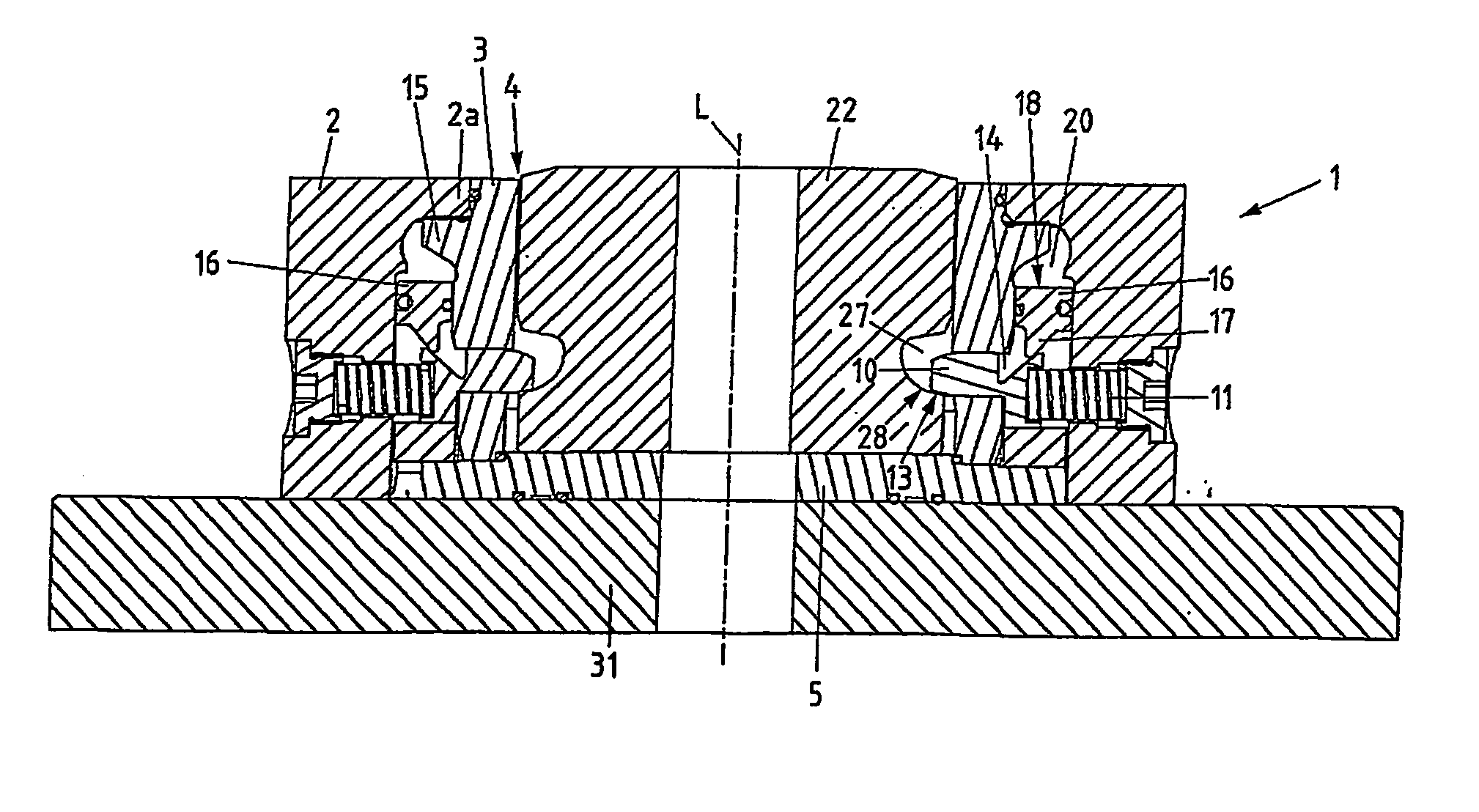
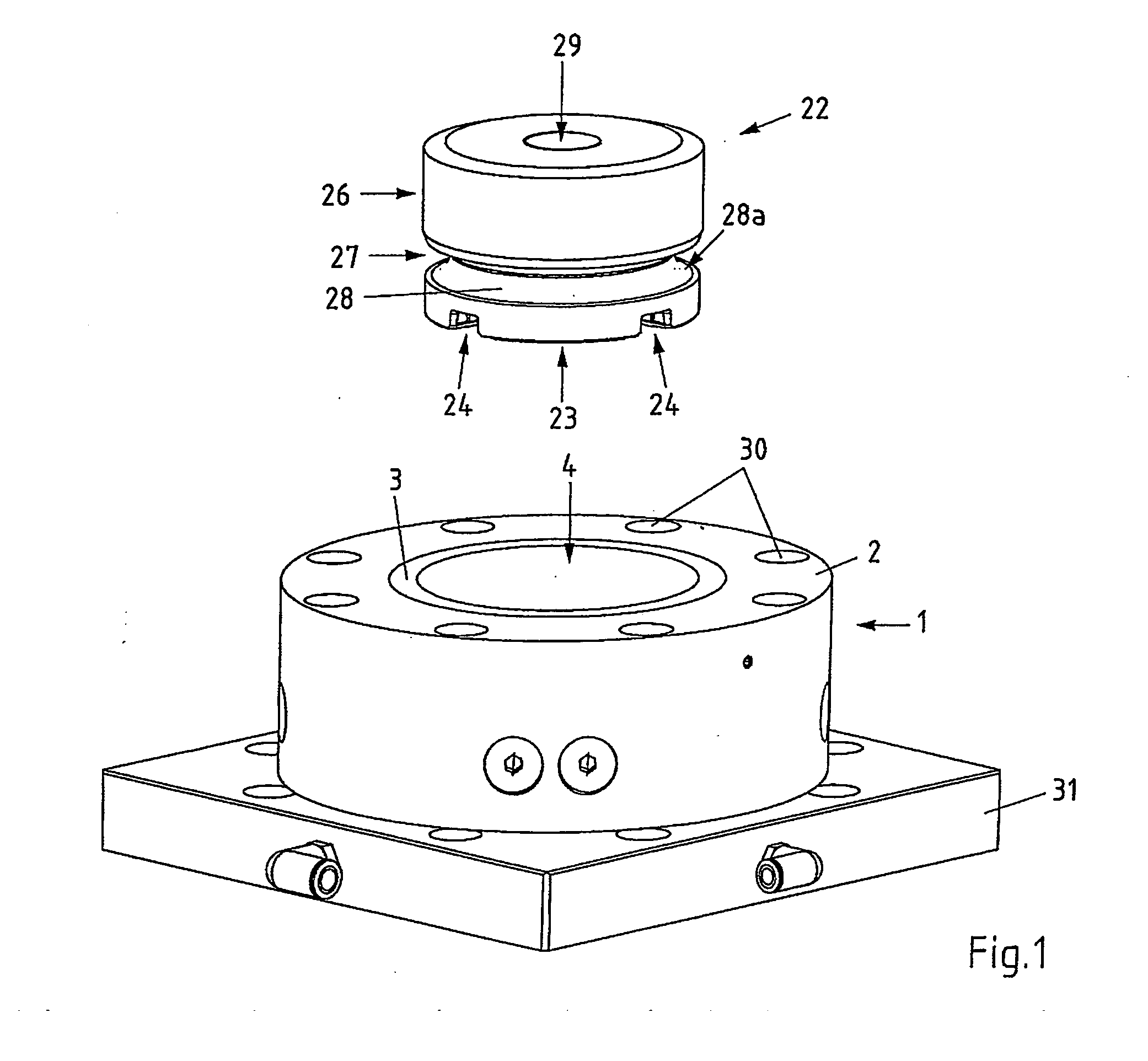
[0019]Referring now to FIG. 1 there is illustrated a view in perspective of a clamping fixture comprising a chuck 1 and a workpiece pallet 22. The chuck 1 is secured to a base plate 31, but it is just as possible that the chuck 1 is directly secured to the machine table. The workpiece pallet 22 serves to mount workpieces repeatedly precisely located on the chuck 1. However, the term workpiece pallet in the present context is not at all to be understood as only serving to mount workpieces, since tools and the like can be secured just as well.

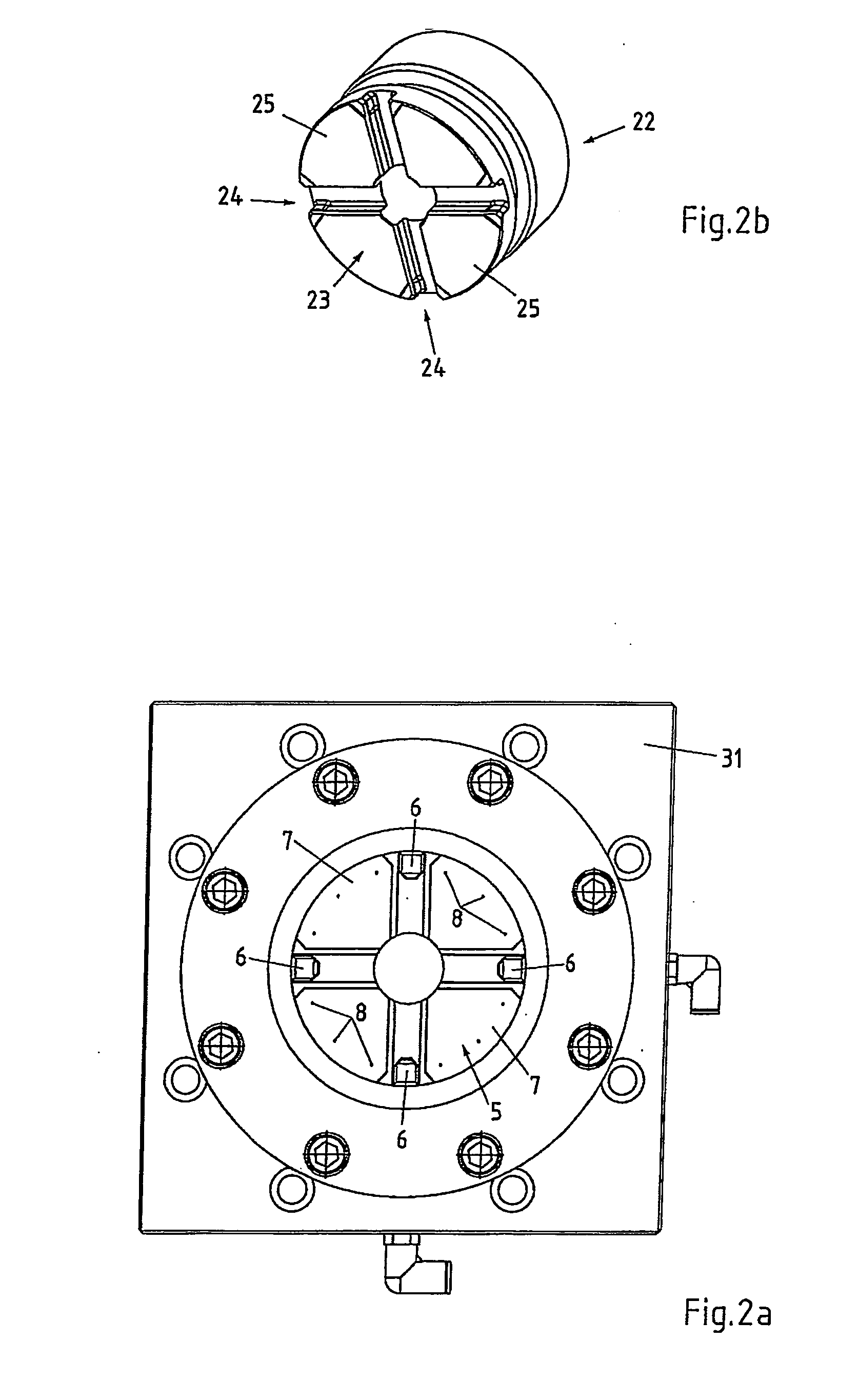
[0020]The chuck 1 comprises a cylindrical base body 2 lined with a liner 3. This liner 3 circumscribes a central aperture 4 serving to mount the workpiece pallet 22 configured substantially cylindrical. The flat underside 23 of the workpiece pallet 22 features centering grooves 24 for engaging centering cams arranged on the chuck 1 when the workpiece pallet 22 is located on the chuck 1. The dead fit of the centering cams engaging the centering gr...


PUM

PropertyMeasurementUnit
tensileaaaaaaaaaa
circumferenceaaaaaaaaaa
forceaaaaaaaaaa

Abstract

A clamping fixture comprises a chuck (1) and a workpiece pallet (22) releasably located thereon. The chuck (1) is provided with a clamping mechanism for locating the workpiece pallet (22). The clamping mechanism comprises a plurality of clamping members configured as plungers (10). The workpiece pallet (22) comprises a clamping surface (28a) running essentially along its shell surface (26) for surface contacting the plungers (10) by its front part (12) provided with a compression surface (13) during clamping.

Description

BACKGROUND[0001]The present invention relates to clamping fixtures, such as clamping fixtures put to use for clamping workpiece pallets provided with a tool or workpiece positionally defined, the chuck usually being fixedly located on a work table of a machine tool or a press whilst the workpiece pallet is repeatedly releasably located precisely positioned at the chuck.[0002]Whilst with known clamping fixtures the resulting compression forces are transmitted mostly via large contact surfaces provided for this purpose, tensile forces in general have to be handled by a clamping mechanism provided with clamping members. Such a clamping mechanism usually features a plurality of spring-loaded clamping balls which when the workpiece pallet is clamped in place engage a clamping surface of a clamping post secured to the workpiece pallet or directly engage the workpiece pallet itself. Although clamping fixtures of this kind have a proven record of success, for some applications it would be a...

Claims


Application Information

Patent Timeline
Patent Type & Authority Applications(United States)
IPC IPC(8): B25B5/16
CPCB23B31/1078B23B31/30B23B2260/126B23B2270/025B23B31/001B23B2270/12B23B2270/28B23Q1/0072B23B2270/027B27G13/10B27G13/12
Inventor SANDMEIER, BRUNO
Owner EROWA
Why Eureka
Try Eureka