Radar display system and method

a technology of a display system and a camera, applied in the field of camera video distribution and display, can solve the problems that software approaches may require substantial resources, and achieve the effect of reducing the cost associated and saving space at the client terminal

Active Publication Date: 2009-02-26
DRS LAUREL TECH PARTNERSHIP D B A DRS LAUREL TECH
View PDF5 Cites 15 Cited by
  • Summary
  • Abstract
  • Description
  • Claims
  • Application Information

AI Technical Summary

Benefits of technology

[0012]The present invention provides a solution to the problem of using special hardware to display radar (e.g., display of scan converted radar with other context image information, such as overlay images or underlay images). For example, using the programmability of graphics processing units to provide for the display of radar, with or without, overlay and / or underlay images, reduces the cost associated with such processes, as well as saves space at the client terminal.

Problems solved by technology

However, as indicated in U.S. Pat. No. 6,806,825, a software approach may require substantial resources since the processor must be able to perform this task as well as all other thin client tasks.

Method used


Image

  • Radar display system and method
  • Radar display system and method
  • Radar display system and method

Examples


Embodiment Construction

[0027]In the following detailed description of exemplary embodiments of the invention, reference is made to the accompanying figures of the drawing which form a part hereof, and in which are shown, by way of illustration, specific embodiments in which the invention may be practiced. It is to be understood that other embodiments may be utilized and structural changes may be made without departing from the scope of the present invention.

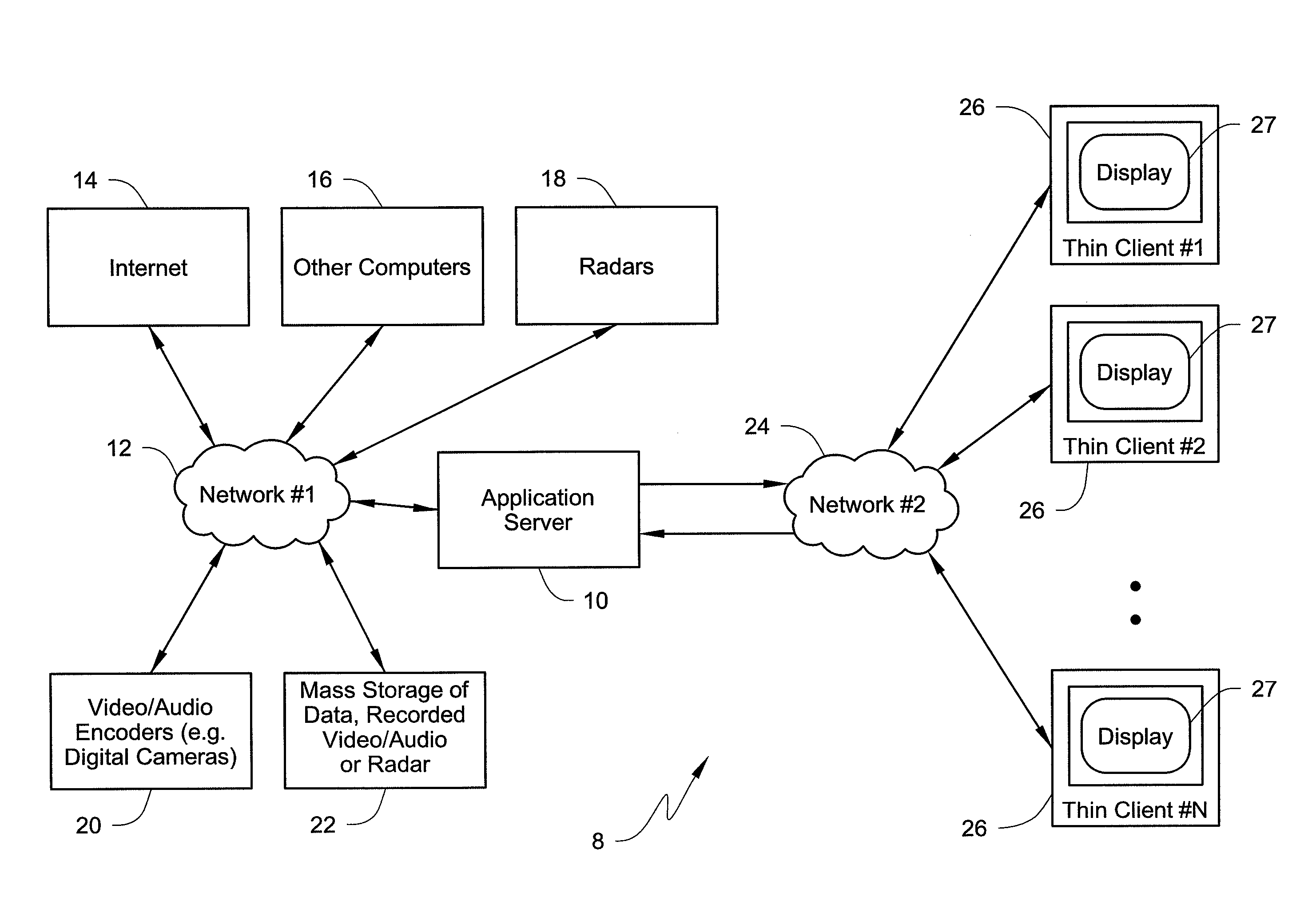
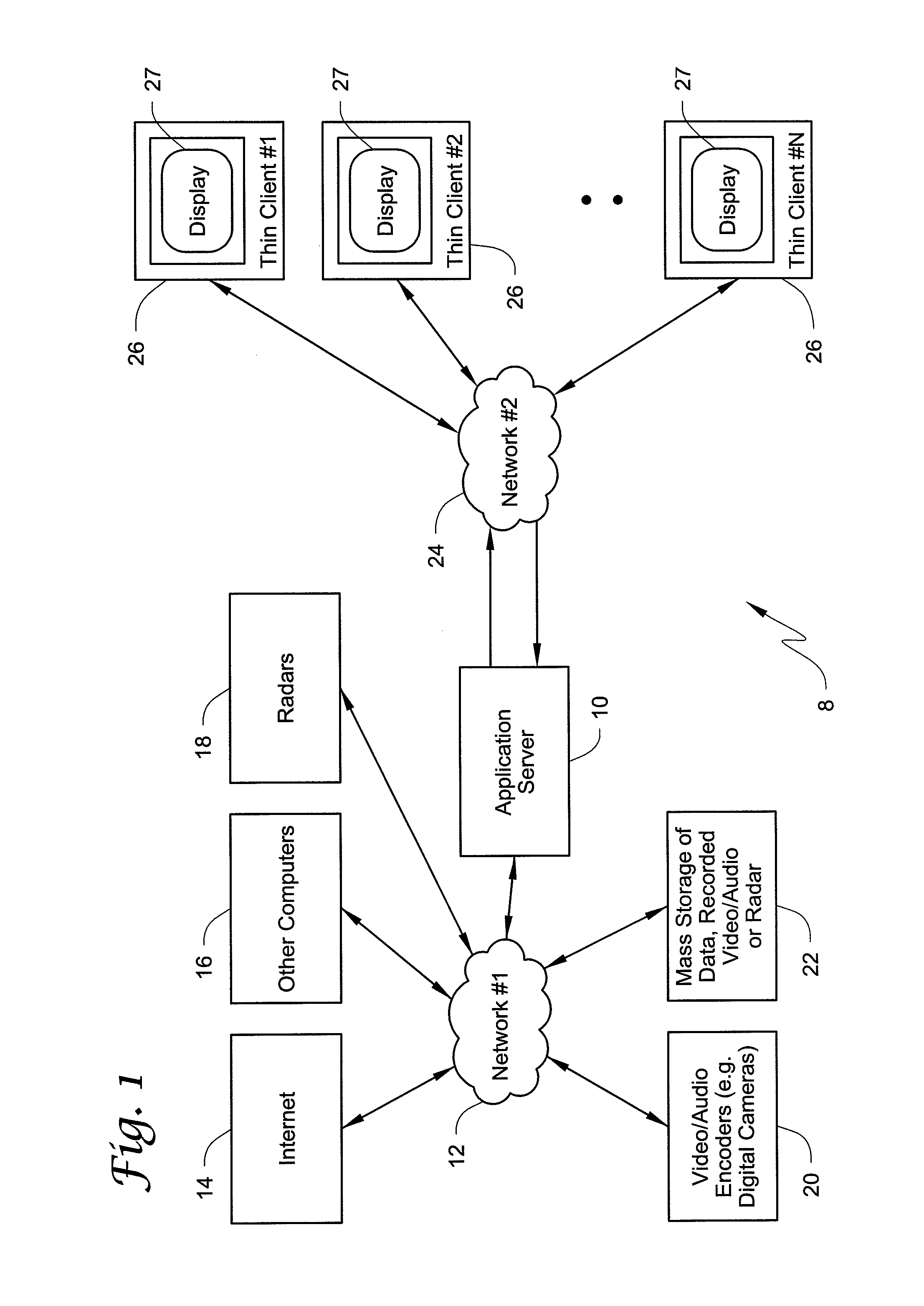
[0028]FIG. 1 shows a block diagram of one exemplary embodiment of a radar display system architecture 8. The radar display system architecture 8 includes an application server 10 that is located between two networks or network segments 12 and 24. One will recognize from the description herein that the system may be implemented using multiple application servers. The network or network segment 12 provides access to an array of networked services such as, but not limited to, the Internet 14, other computers 16, radars 18, audio and video encoders 20, or ...


PUM


Abstract

Radar display methods and systems include a display processing apparatus that includes a central processing unit and a programmable graphics processing unit. A rendering function program executable by the programmable graphics processing unit under control of the central processing unit generates a plurality of sequential display image frames for use in displaying at least a radar image on a display (e.g., by applying a decaying function to an accumulated radar history image frame and updating the accumulated radar history image frame).

Description

CROSS-REFERENCE TO RELATED APPLICATIONS[0001]This application claims the benefit of U.S. Provisional Application Serial No. 60 / 959,334 filed 13 Jul. 2007, entitled “Radar Display System and Method,” which is incorporated herein by reference in its entirety.BACKGROUND[0002]The present invention relates generally to radar video distribution and display. More particularly, the present invention relates to systems and methods of distributing and managing digitized radar video for display, e.g., display of scan converted radar with other information, such as overlay images or underlay images.[0003]Computer system user interfaces have had several different architectures since their invention. Early computers used lights and buttons, or punch cards and printers to provide the user interface. Mainframe computers have traditionally used cathode ray tube (CRT) terminals that provided the user interface. The mainframe system was characterized by the fact that application programs run on the ce...

Claims


Application Information

Patent Timeline
Patent Type & Authority Applications(United States)
IPC IPC(8): G01S13/00
CPCG01S7/003G01S7/046G01S7/298G01S7/22G01S7/066
Inventor ANDRUSIAK, MARTIN J.BENJAMIN, SCOTT J.GOHMAN, JOHN L.DUNNE, KENNETH D.
Owner DRS LAUREL TECH PARTNERSHIP D B A DRS LAUREL TECH
Why Eureka
Try Eureka