Method for signal jitter detections based on time-frequency domain analysis

a time-frequency domain and signal jitter technology, applied in the direction of transmission monitoring, line-transmission details, digital transmission, etc., can solve the problems of transient jitter frequency and moment detection that cannot be realized by the prior art and the measurement of jitter frequency variation and transient jitter frequency and moment detection

Inactive Publication Date: 2009-02-26
WU WEI
View PDF1 Cites 7 Cited by
  • Summary
  • Abstract
  • Description
  • Claims
  • Application Information

AI Technical Summary

Benefits of technology

[0023]Compared with prior art, the present invention method has prominent advantages. By means of time-frequency domain analysis of the signal jitter time trend, the invention method indicates the jitter frequency variation in time and detects the transient jitter frequency and moment that may be helpful for circuit design engineer to trace the origin of the jitter and to analyze multi-effects among various frequencies components, and to diagnose the interference source and to protect the interference. Such the jitter frequency variation measurement and transient jitter frequency and moment detection are unrealizable by the prior art.

Problems solved by technology

Such the jitter frequency variation measurement and transient jitter frequency and moment detection are unrealizable by the prior art.

Method used


Image

  • Method for signal jitter detections based on time-frequency domain analysis
  • Method for signal jitter detections based on time-frequency domain analysis
  • Method for signal jitter detections based on time-frequency domain analysis

Examples


embodiment 1

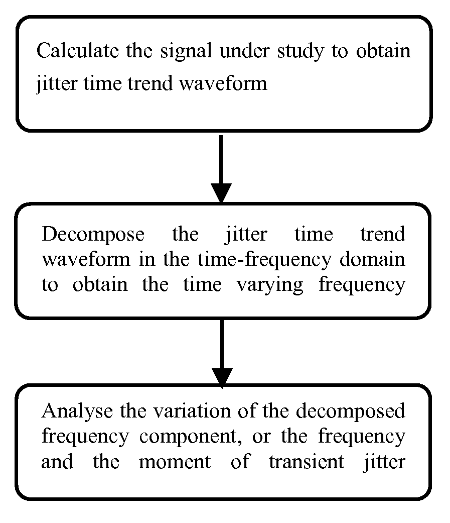
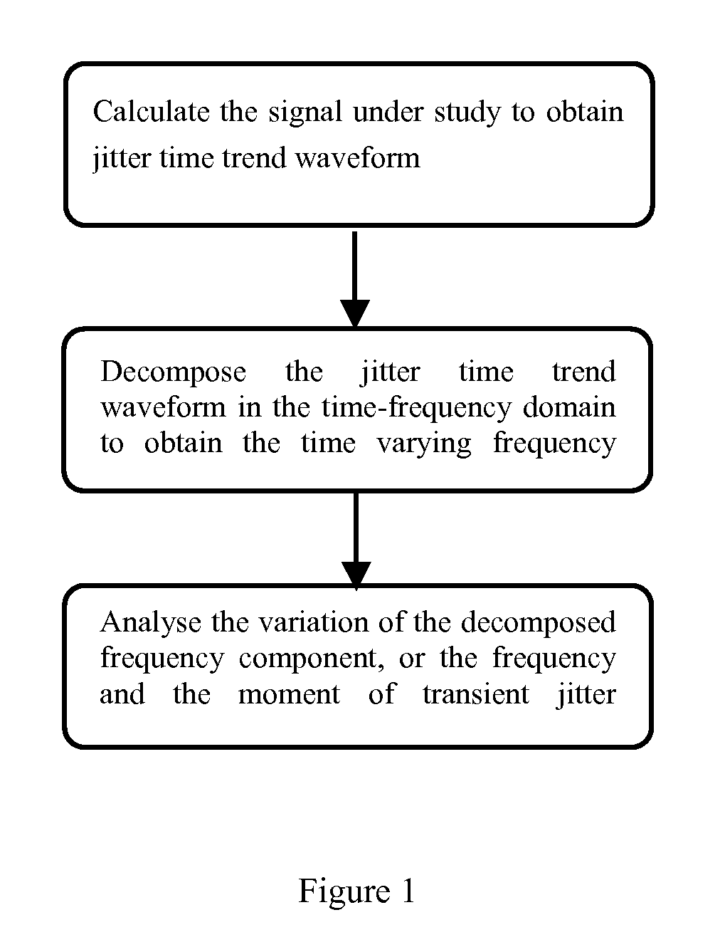
[0027]Best mode This embodiment extracts the transient jitter in time-frequency domain The experimental signal is the serial pulse data acquired from an AFS 1016 Fast Ethernet Switch by an oscilloscope. FIG. 1 shows the flow chart of the process of the invention method comprising:[0028](1) Calculate the signal to obtain jitter time trend waveform. Various jitter calculation algorithms that illustrate the result in the format of time trend can be used. In this Best Mode Embodiment, the signal from the Switch is acquired by a digital oscilloscope and PJ of acquired signal is calculated according to (2), resulting at waveform illustrated at FIG. 2 top frame. It is well-know to the designer with ordinary skill in the pertinent art, there are many oscilloscope products integrated the jitter analysis function and can be used to acquire data from the signal and calculate the jitter time trend waveform.[0029](2) Decompose the PJ time trend waveform into time-frequency domain. Signal transf...

embodiment 2

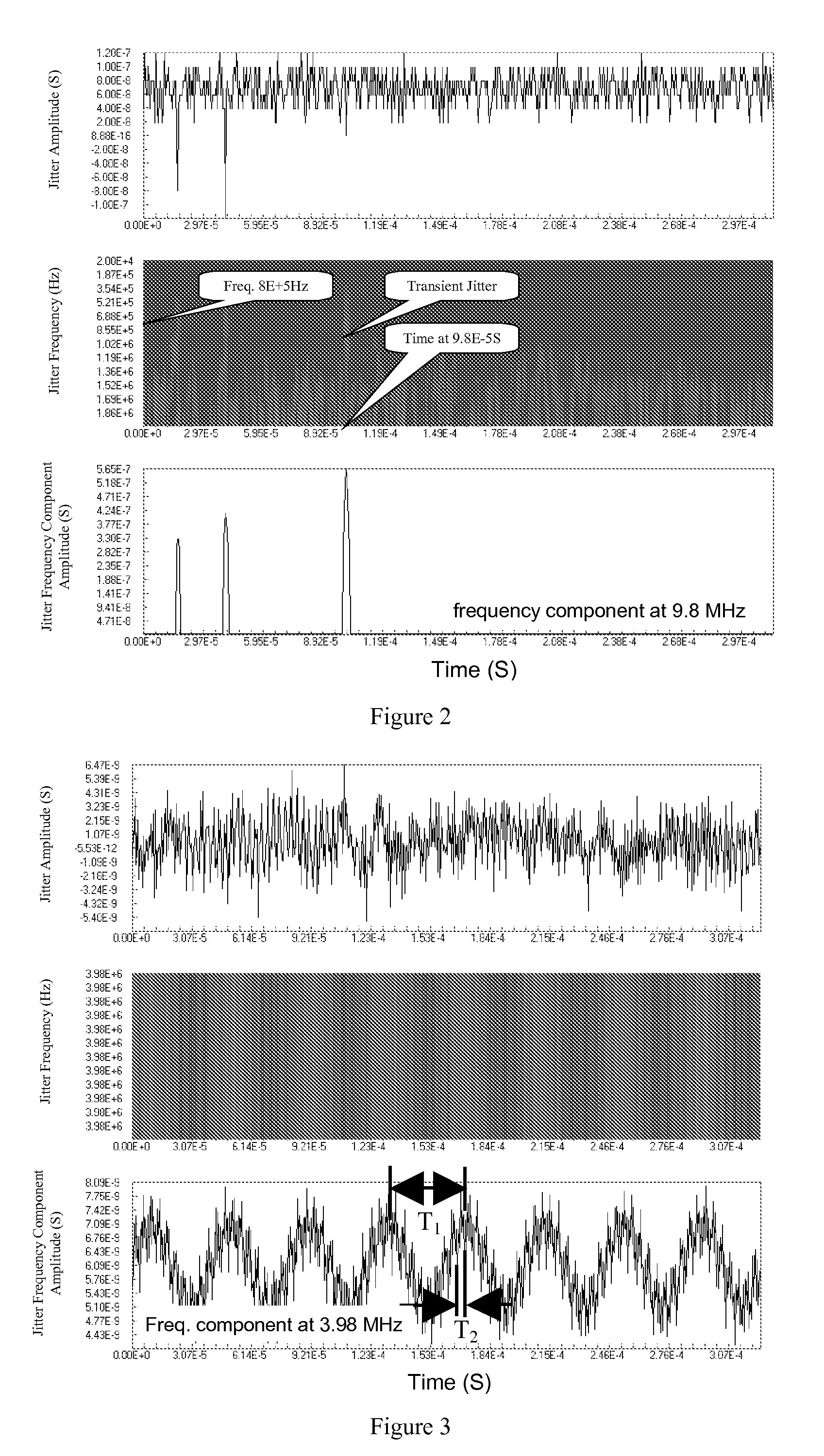
[0035]Best mode This embodiment extracts the jitter frequency time trend variation of the signal. Again, following the procedure illustrated in FIG. 1:

[0036](1) Calculate the signal under study into the jitter time trend waveform. The experimental signal is the serial pulse data that is acquired from an AFS 1016 Fast Ethernet Switch, recorded and calculated the Time Interval Error (TIE) according to (3) by an oscilloscope, resulting at the signal TIE trend waveform illustrated in the top frame of FIG. 3.

[0037](2) The signal TIE time trend waveform is decomposed into the time-frequency domain. In this embodiment 2, the Short-Term Fourier Transform (STFT) is used:

Sƒ(u,Ω))=∫−∞+∞ƒ(t)g(t−u)e−taxdt  (6)

where[0038]g(t−u) is the window function;[0039]U is the shifting factor;[0040]ƒ(t) is the time domain signal being transformed; and[0041]Sƒ(u,Ω)) is the STFT coefficient after transforming.

[0042]It is well-know for the designer with ordinary skill in the pertinent art that STFT transforms ...


PUM


Abstract

A jitter measuring method that helps the electronic system designer to reduce system jitter by tracing the jitter frequency variation and by detecting the transient jitter. The method includes below procedure: first, calculate the jitter of the signal to obtain signal jitter time trend waveform; then, decompose the jitter time trend waveform in the time-frequency domain to obtain the time varying frequency; after that, observe the decomposed results in time-frequency domain to trace out jitter frequency variation in time or to trace out transient jitter frequency and moment.

Description

CROSS-REFERENCE TO RELATED APPLICATION[0001]This application claims priority under 35 U.S.C. § 119 to China Patent Application No. 2007100859392, filed on Feb. 27, 2007, in the China Intellectual Property Office, the entire contents of which are hereby incorporated by reference.FIELD OF THE INVENTION[0002]The present invention relates to a signal Jitter detection method.BACKGROUND OF THE INVENTION[0003]Jitter is defined by: The deviation of the significant instances of a signal from their ideal location in time. Jitter can be caused by electronic device electronic noise, thermal noise, instability of the circuit, signal transition loss and environment interference, resulting at increasing data communication error and reducing the system stability. As signalling rates climb above 2 GHz nowadays, the timing margins associated with today's high-speed serial buses and data links reveal that a tighter control of jitter is needed throughout the system design.[0004]The currently used jitte...

Claims


Application Information

Patent Timeline
Patent Type & Authority Applications(United States)
IPC IPC(8): H04B17/00
CPCH04L1/205
Inventor WU, WEI
Owner WU WEI
Why Eureka
Try Eureka