Venting valve to be used in venting bores of vulcanization molds

a technology of vulcanization molds and venting valves, which is applied in the direction of functional valve types, tires, domestic articles, etc., can solve the problem of incomplete vulcanization of semi-finished products

Active Publication Date: 2009-02-26
GLEBUS ALLOYS EURO S R O
View PDF30 Cites 12 Cited by
  • Summary
  • Abstract
  • Description
  • Claims
  • Application Information

AI Technical Summary

Benefits of technology

[0013]The part of the valve sleeve, which is oriented to the cavity of the vulcanization mold, has greater outer diameter than the part of the valve sleeve, which is located more closely to the outer side of the vulcanization mold, and the part of the valve sleeve having smaller diameter is provided with longitudinal notch grooves or opening

Problems solved by technology

Insufficient removal of air from the vulcanization mold causes faults on the finished products, both depressions are formed in the tread area and the material may be insufficiently heated and thus vulcanization of the semi-fini

Method used


Image

  • Venting valve to be used in venting bores of vulcanization molds
  • Venting valve to be used in venting bores of vulcanization molds
  • Venting valve to be used in venting bores of vulcanization molds

Examples


example 1

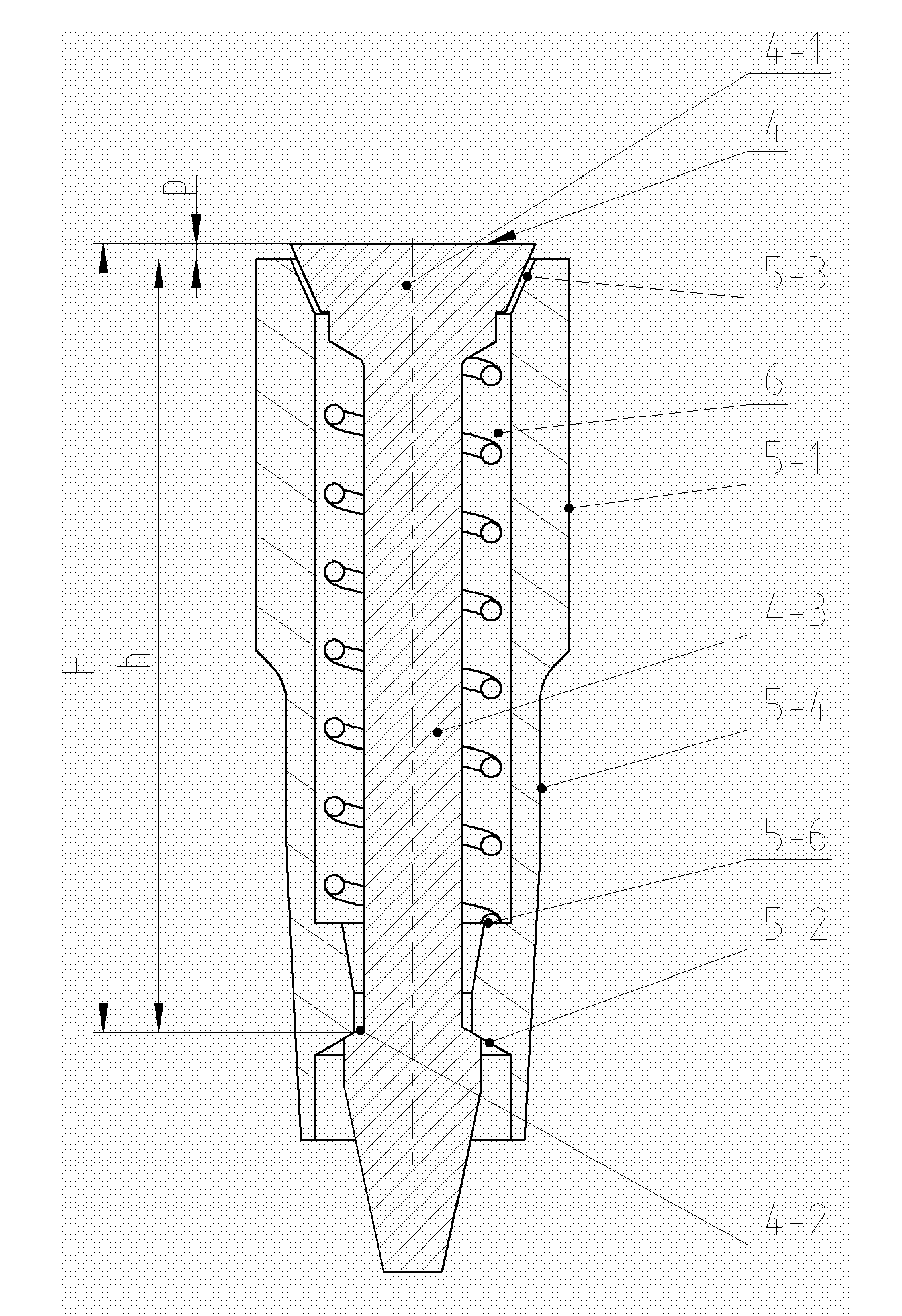
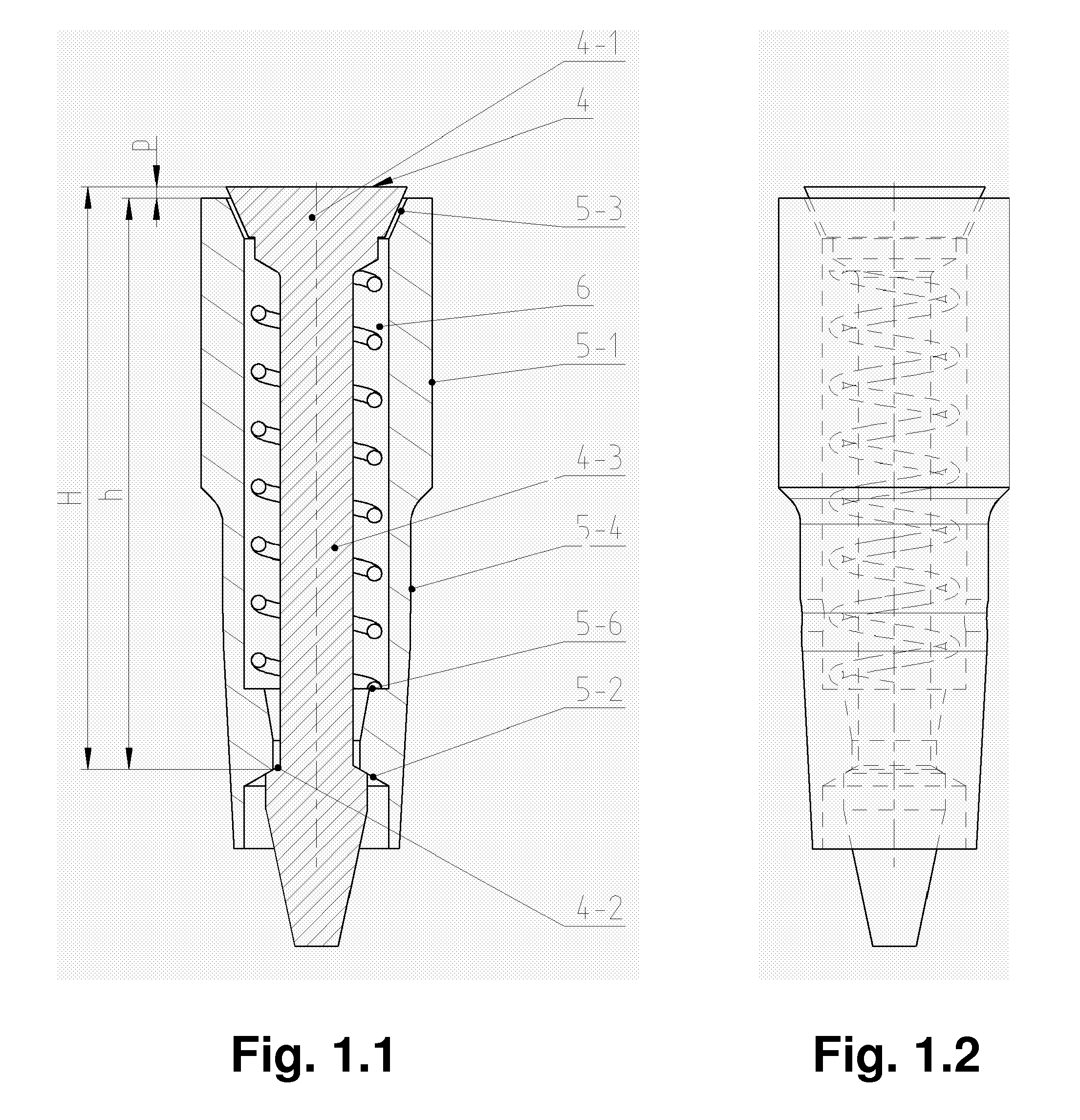
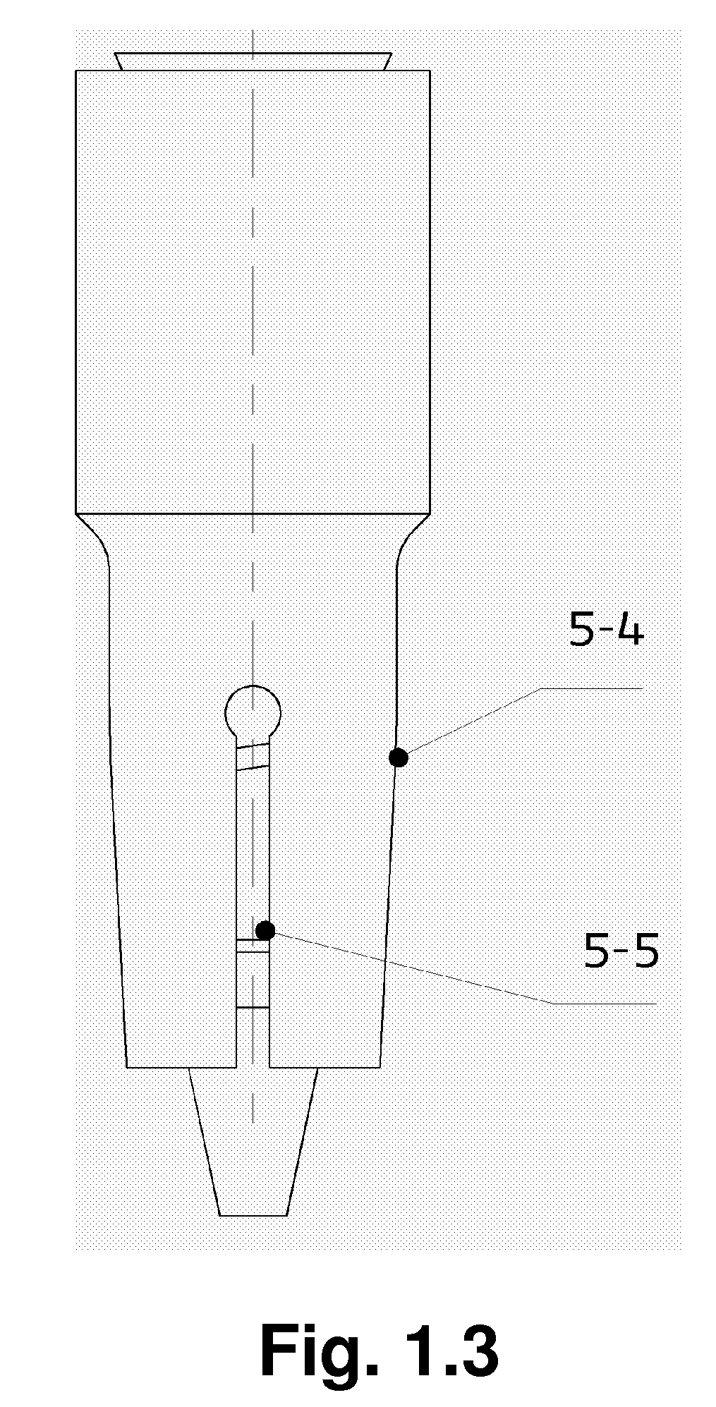
[0025]The vent valve, shown in FIG. 1.1, consists of a valve sleeve (5), which has cylindrical shape and is provided with a cavity. The outer diameter of that part (5-1) of the valve sleeve (5), which, when used in the venting bore of a vulcanization mold, is located more closely to the inner space of the mold, is essentially the same as diameter of the bore in the vulcanization mold for embedding the valve, and is greater than the outer diameter of the second part (5-4) of the sleeve (5), which is oriented outwards of the mold. This part (5-4) of the sleeve (5) having smaller outside diameter is provided with at least two longitudinally oriented notch grooves (5-5) (FIG. 1.3), running from the sleeve end to its part (5-1) having greater outer diameter. These notch grooves allow air to escape from the vulcanization mold into the space created between the cylindrical bore in the vulcanization mold and the tapered part (5-4) of the valve sleeve (5) and further away from the vulcanizat...

example 2

[0030]The vent valve, shown in FIG. 2.1, consists of a valve sleeve (5) of cylindrical shape, which is provided with a cavity. The valve sleeve (5) is formed by tight connection, for example by pressing together two hollow cylindrical parts, namely a machined rotational body as part (5-1) having greater outer diameter, and a drawn piece (tapered part (5-4)) having at least in a part of it smaller outer diameter in comparison with the above part. Outer diameter of that part of the valve sleeve (5), which when used in the venting bore of the vulcanization mold is located more closely to the inner space of the mold, is essentially the same as diameter of the bore for embedding the vent valve of the vulcanization mold, so it has greater diameter than the outer diameter of the second part (5-4) of the valve sleeve (5), which is located closer to the outer space. This part (5-4) of the valve sleeve (5) having smaller outer diameter is provided with two longitudinal openings, while materia...

example 3

[0034]FIG. 3.1 shows a further embodiment of the vent valve, which consists of a valve sleeve (5) of cylindrical shape, which is provided with a cavity. Outer diameter of that part (5-1) of the valve sleeve (5), which, when used in the venting bore of a vulcanization mold, is located more closely to the inner space of the mold, is essentially the same as diameter of the bore in the vulcanization mold for embedding the valve, and is greater than the outer diameter of the second part (5-4) of the sleeve (5), which is oriented outwards of the mold. This part (5-4) of the valve sleeve (5) having smaller outside diameter is provided with at least two longitudinal notch grooves (5-5) (FIG. 3.2), running from the lower (outer) end of the sleeve (5) to its part (5-1) having greater outer diameter. These notch grooves (5-5) allow air to escape from the vulcanization mold into the space created between the cylindrical bore in the vulcanization mold and the tapered part (5-4) of the valve slee...


PUM

PropertyMeasurementUnit
Pressureaaaaaaaaaa
Diameteraaaaaaaaaa
Flexibilityaaaaaaaaaa

Abstract

Vent valve for venting bores of vulcanization moulds, especially for the tread profile area, consisting of a valve sleeve (5), in which a valve insert (4) and a wound spring (6) are movably located, wherein the valve insert (4) consists of a valve shank (4-3), which is at one end equipped with a disk (4-1) and at the other end with a conical surface (4-2) changing into backwards oriented conical end, and the movement of the valve insert (4) is controlled by a delimiter of opening the valve. Inner surface of the valve sleeve (5) is in its part (5-4) located further away from disk (4-1) provided with conical surface (5-2), away from the disk (4-1), and the delimiter of opening the valve is formed by two mutually cooperating conical surfaces (4-2, 5-2) or parts of conical surfaces (4-2, 5-2), wherein the conical surface (4-2) formed at the end of the valve shank (4-3) of the valve insert (4) is oriented against the conical surface (5-2) or part of conical surface (5-2) of the valve sleeve (5).

Description

CROSS-REFERENCE TO RELATED APPLICATIONS[0001]This application is a national stage of PCT International application no. PCT / SK2007 / 050007 filed Feb. 26, 2007, which claims priority to Slovakian application Serial No. PP 0044-2006 filed Mar. 3, 2006, herein incorporated by reference.TECHNICAL FIELD[0002]The invention concerns a vent valve to be used in venting bores of vulcanization molds for production of technical rubber products, especially for tire production. Vent valves according to the present invention are particularly suitable to be used in vulcanization molds for tire production for the tread area to prevent forming depressions or lateral flow projections.BACKGROUND[0003]Molds for tire vulcanization are equipped with venting bores, through which air escapes, so that semi-finished tire placed in the mold by pressure acting from the side of mold cavity can acquire the shape corresponding to the tool inserted in the vulcanization mold. This unvulcanized semi-finished product mo...

Claims


Application Information

Patent Timeline
IPC IPC(8): B29C45/34
CPCB29C33/10B29D30/0662Y10S425/812F16K24/04B29D2030/0617
Inventor HAJDUCH, JAROSLAV
Owner GLEBUS ALLOYS EURO S R O
Why Eureka
Try Eureka