Fuel gas feeding device and control method therefor

a fuel gas feeding device and fuel cell technology, applied in the field of fuel cell systems, can solve the problems of damage to the pressure reducing valves and the passage, and achieve the effect of reducing the amount of fuel gas consumed by the fuel cell and reducing the excessive pressur

Inactive Publication Date: 2009-02-26
TOYOTA JIDOSHA KK
View PDF8 Cites 14 Cited by
  • Summary
  • Abstract
  • Description
  • Claims
  • Application Information

AI Technical Summary

Benefits of technology

[0004]The object of the present invention is thus to solve the drawbacks of the background art discussed above, and to suppress an excessive rise of pressure between two pressure reducing valves if the amount of fuel gas consumed by a fuel cell decreases.

Problems solved by technology

Thus, in the background art, there is a risk of damage to the two pressure reducing valves and to the passage between the two pressure reducing valves, and it is necessary to improve pressure resistance of these portions.

Method used


Image

  • Fuel gas feeding device and control method therefor
  • Fuel gas feeding device and control method therefor
  • Fuel gas feeding device and control method therefor

Examples


modification example

A-4. Modification Example of First Embodiment

[0087]FIG. 5 is a flowchart showing the procedure for control of the second pressure reducing valve 218 in a Modification Example of the First Embodiment. FIG. 5 is substantially similar to FIG. 3, except that Steps S112 and S114 are added. In association therewith, Steps S106a and 108a are modified.

[0088]In the Modification Example, if it is determined in Step S106a that the pressure Pb in the second partial passage 121b is less than the first threshold value Pb_max, the process advances to Step S112.

[0089]In Step S112, the control circuit 600 determines whether the pressure Pb acquired in Step S106 is equal to or less than a second threshold value Pb_min. The second threshold value Pb_min is a value smaller than the first threshold value Pb_max. If the pressure Pb is equal to or less than the second threshold value Pb_min, the process advances to Step S114. On the other hand, if the pressure Pb is greater than the second threshold value...

second embodiment

B. Second Embodiment

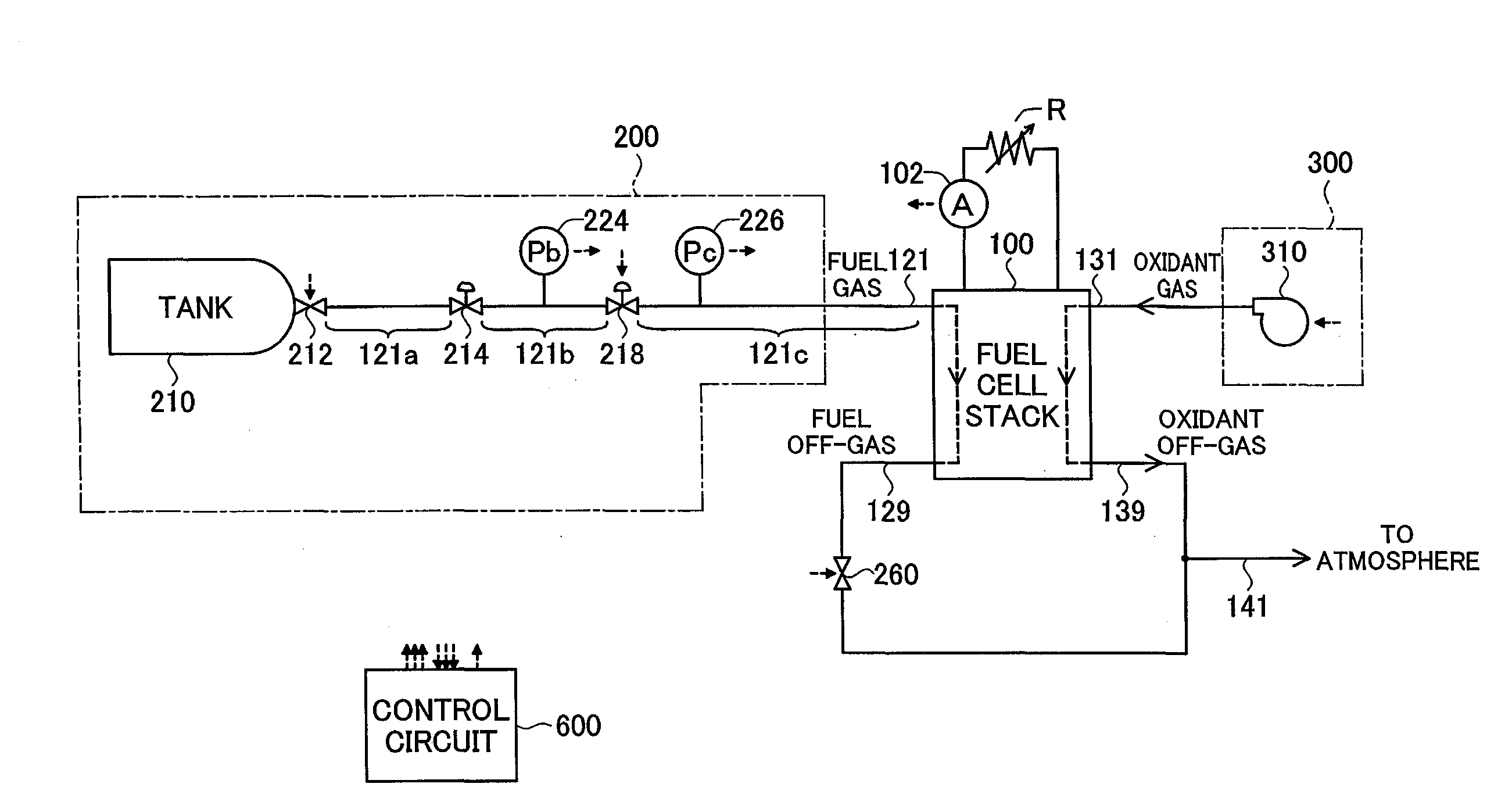
[0098]FIG. 7 is an illustration showing the general configuration of the fuel cell system in the Second Embodiment. FIG. 7 is substantially similar to FIG. 1, except that the ammeter 102 is omitted. Also, the second pressure reducing valve 218B of the fuel gas supply system 200B is modified. Specifically, the target pressure of the second pressure reducing valve 218B is set to a fixed value, and is not adjustable by the control circuit 600.

[0099]FIGS. 8(A) and 8(B) are illustrations typically showing the internal structure of the second pressure reducing valve 218B in the Second Embodiment. FIG. 8(A) shows the second pressure reducing valve 218B when set to the open state, and FIG. 8(B) shows the second pressure reducing valve 218B when set to the closed state.

[0100]As illustrated, the second pressure reducing valve 218B includes an upper housing 410, a lower housing 420, a diaphragm 430, a needle valve 440, a seat portion 450, an upper spring 461, and a lower sp...

modification example 1

B-1. Modification Example 1 of Second Embodiment

[0115]FIG. 10 is an illustration showing a second pressure reducing valve 218B1 in Modification Example 1 of the Second Embodiment. As illustrated, in Modification Example 1, a needle valve 440B1 is modified. Specifically, three convex portions 444 of semi-spherical shape are formed in the distal end portion of the needle valve 440B1. The convex portions 444 may be affixed to the needle valve 440B1 by welding, for example.

[0116]Where Modification Example 1 is employed as well, the second pressure reducing valve 218B, in the state of maximum constriction, can cause fuel gas to pass via flow passages formed by the convex portions 444.


PUM

PropertyMeasurementUnit
pressureaaaaaaaaaa
pressure resistanceaaaaaaaaaa
electric currentaaaaaaaaaa

Abstract

To provide a technique to suppress an excessive rise of pressure between two pressure reducing valves if the amount of fuel gas consumed by a fuel cell stack decreases. A fuel gas supply apparatus comprises: a gas passage in which fuel gas to be supplied to a fuel cell stack flows; a first pressure reducing valve provided to the gas passage; a second pressure reducing valve provided to the gas passage and disposed at a downstream side of the first pressure reducing valve; a setting module that sets a value of target pressure at a downstream side of the second pressure reducing valve, to a value depending on a consumed amount of fuel gas consumed by the fuel cell stack; and a modifying module that, if the consumed amount decreases by a prescribed amount or more, modifies the value of target pressure of the second pressure reducing valve to a value greater than a corresponding value that corresponds to the consumed amount subsequent to the decrease.

Description

TECHNICAL FIELD[0001]The present invention relates to a fuel cell system, and in particular relates to a fuel gas supply apparatus for supplying fuel gas to a fuel cell.BACKGROUND ART[0002]A fuel cell system includes a fuel cell stack, a fuel gas supply system for supplying a fuel gas to the fuel cell stack, and an oxidant gas supply system for supplying an oxidant gas to the fuel cell stack. The fuel gas supply system includes, for example, a tank for storing the fuel gas under high pressure, and a fuel gas passage connecting the tank with the fuel cell stack. The fuel gas supply system typically includes a first pressure reducing valve disposed on the upstream side of the fuel gas passage and a second pressure reducing valve disposed on the downstream side of the fuel gas passage. Each of the pressure reducing valves has the function of adjusting the pressure at the downstream side thereof to a target pressure.[0003]Now, in the event of a sudden decrease of the amount of fuel gas ...

Claims


Application Information

Patent Timeline
Patent Type & Authority Applications(United States)
IPC IPC(8): H01M8/04
CPCH01M8/04089H01M8/04201H01M8/04261H01M8/04388Y02E60/50H01M8/04798H01M2250/20Y02T90/32H01M8/04589H01M8/04197Y02T90/40
Inventor KATANO, KOJI
Owner TOYOTA JIDOSHA KK
Why Eureka
Try Eureka