Variable Sampling Interval for Blood Analyte Determinations

a sampling interval and blood analyte technology, applied in the field of multiple measurement of analytes, can solve the problems of increasing labor and complexity of tight glycemic control protocols, increasing the risk of neurological damage of patients exposed to hypoglycemia for more than 30 minutes, and difficult adoption, so as to reduce operator interaction and operator error, improve patient safety, and improve measurement efficiency

Inactive Publication Date: 2009-02-26
ROBINSON MARK RIES +2
View PDF15 Cites 198 Cited by
  • Summary
  • Abstract
  • Description
  • Claims
  • Application Information

AI Technical Summary

Benefits of technology

[0013]The present invention comprises methods and apparatuses that can provide measurement of glucose with variable intervals between measurements, allowing more efficient measurement with greater patient safety. A method according to the present invention can comprise measuring the value of an analyte such as glucose at a first time; determining a second time from a patient condition, an environmental condition, or a combination thereof; then measuring the value of the analyte at the second time (where the second time can be expressed as an interval after the first time, an absolute time, or a time indicated when certain patient

Problems solved by technology

As research continues to show the benefits of driving patient's blood glucose levels even lower these tight glycemic control protocols have become increasingly labor intensive and complicated.
Although hospitals are responding to the identified clinical need, adoption has been difficult with current technology due to two principal reasons.
Patients exposed to hypoglycemia for greater than 30 minutes have significant risk of neurological damage.
IV insulin administration with only intermittent glucose monitoring (typically hourly by most TGC protocols) exposes patients to increased risk of hypoglycemia.
In addition,

Method used


Image

  • Variable Sampling Interval for Blood Analyte Determinations
  • Variable Sampling Interval for Blood Analyte Determinations
  • Variable Sampling Interval for Blood Analyte Determinations

Examples


example embodiment

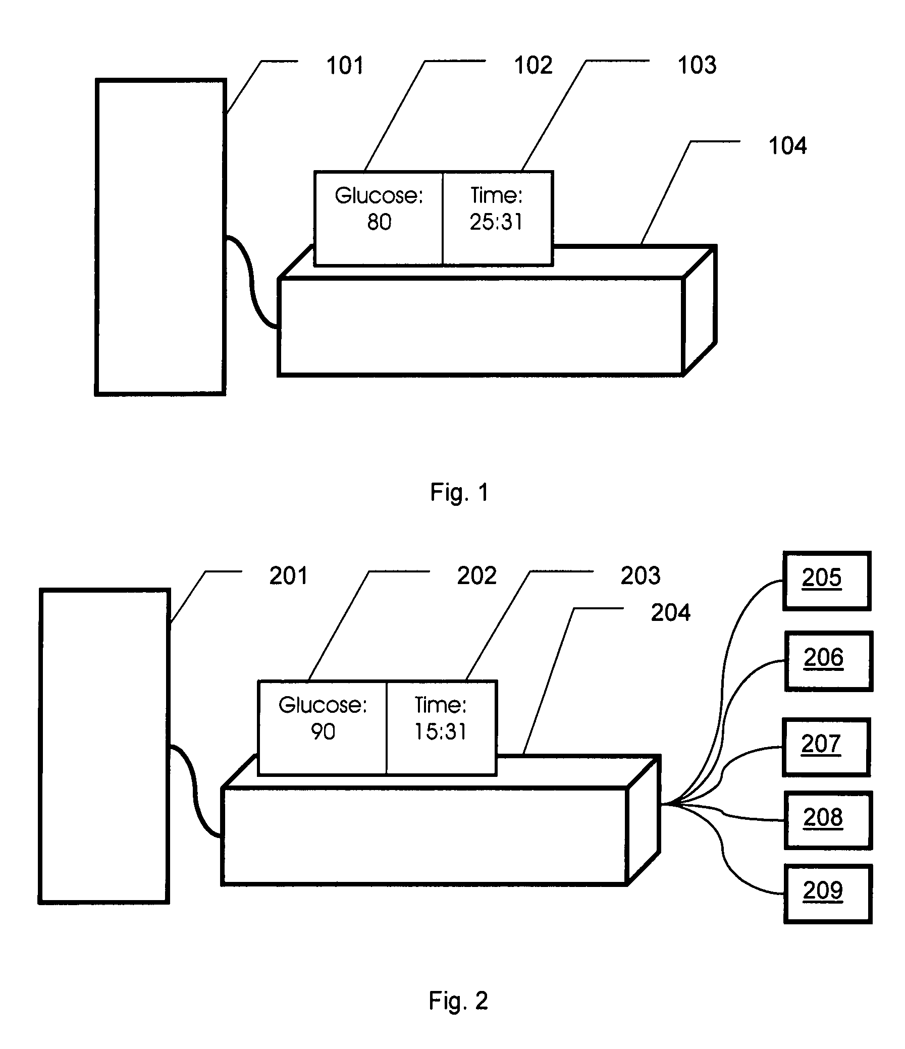
[0059] FIG. 10 shows a generic embodiment of the system. The operational implementation of the system requires interaction with the patient for the procurement of a blood measurement. This measurement value is then communicated via a variety of possible means to the system that determines the time for the next measurement.

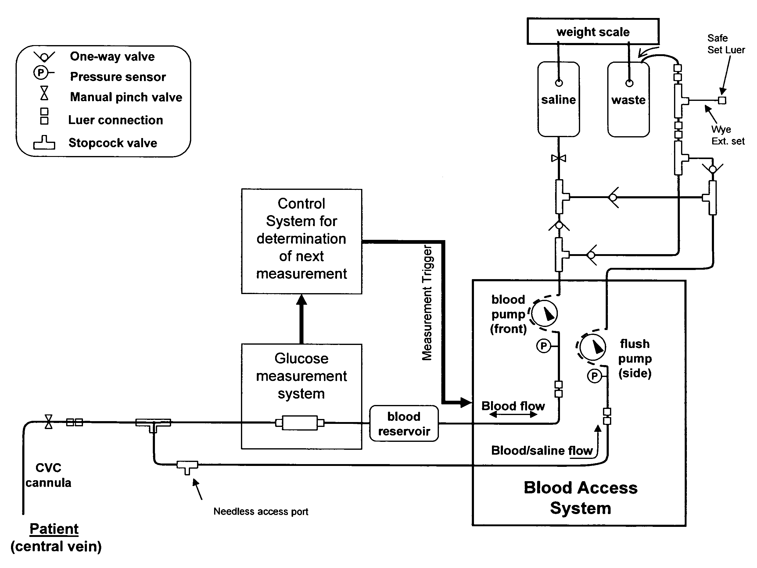
[0060]Example Embodiment. FIG. 11 shows an example system in operation on an automated blood removal system. In operation the module labeled “control system for determination of next measurement” initiates the procurement of a glucose measurement. The blood access system initiates blood sample procurement. The blood is presented to the glucose measurement system and a glucose value obtained. The glucose value or related information is communicated to the control system and the time for the next sample determined. The exact methods used for sample procurement can include a manual sample, noninvasive sample, indwelling measurements, or invasive measurement methods. T...


PUM


Abstract

The present invention provides methods and apparatuses that can provide measurement of glucose with variable intervals between measurements, allowing more efficient measurement with greater patient safety. A method according to the present invention can comprise measuring the value of an analyte such as glucose at a first time; determining a second time from a patient condition, an environmental condition, or a combination thereof; then measuring the value of the analyte at the second time (where the second time can be expressed as an interval after the first time, an absolute time, or a time indicated when certain patient or environmental conditions, or both, are reached or detected). The second time can be determined, as an example, from a comparison of the analyte value at the first time with a threshold. The interval between the first time and the second time can be related to the difference between the analyte value at the first time and the threshold; e.g., the closer to the threshold, the closer the two measurement times. The invention can be used with automated measurement systems, allowing the system to determine measurement times and automatically make measurements at the determined times, reducing operator interaction and operator error.

Description

CROSS-REFERENCE TO RELATED APPLICATIONS[0001]This application is related to U.S. provisional application 60 / 791,719, filed Apr. 12, 2006, and to U.S. provisional application 60 / 737,254, filed Nov. 15, 2006, each of which is incorporated herein by reference.FIELD OF THE INVENTION[0002]This invention relates to the field of the measurement of blood analytes, and more specifically to multiple measurements of analytes such as glucose in blood that has been temporarily or permanently removed from a body.BACKGROUND OF THE INVENTION[0003]Many peer-reviewed publications have demonstrated that tight control of blood glucose significantly improves critical care patient outcomes. Tight glycemic control (TGC) has been shown to reduce surgical site infections by 60% in cardiothoracic surgery patients and reduce overall ICU mortality by 40% with significant reductions in ICU length of stay. See, e.g., Furnary Tony, Oral presentation at 2005 ADA annual, session titled “Management of the Hospitaliz...

Claims


Application Information

Patent Timeline
IPC IPC(8): A61B5/00G01N33/50G16H40/63G16Z99/00
CPCA61B5/14503A61B5/14532G06F19/3456G06F19/3437G06F19/345G06F19/3406G16H40/63G16H50/50G16H50/20G16Z99/00
Inventor ROBINSON, MARK RIESBORRELLO, MIKEMCMAHON, DAVE
Owner ROBINSON MARK RIES
Why Eureka
Try Eureka