Microprocessor

a microprocessor and microprocessor technology, applied in the field of microprocessors, can solve problems such as problems such as problems such as redundancy brought in the software by such restrictions, and achieve the effect of minimizing the increase in redundancy

Inactive Publication Date: 2009-02-26
RENESAS ELECTRONICS CORP
View PDF6 Cites 33 Cited by
  • Summary
  • Abstract
  • Description
  • Claims
  • Application Information

AI Technical Summary

Benefits of technology

[0022]The microprocessor having such structure in accordance with the third aspect of the present invention can generate the imaginary part of the product of the first and second complex number data by the MADD operation circuit configured in the first operation state, and select the output destination of the imaginary part of the product of the first and second complex number data by the storage area select circuit. Furthermore, the microprocessor in accordance with the third aspect can generate the real part of the product of the first and second complex number data by the MADD operation circuit configured in the second operation state, and select the output destination of the real part of the product of the first and second complex number data by the storage area select circuit. That

Problems solved by technology

The inventors have found out that when a complex operation unit to carry out complex multiplication such as the above-described complex multiplication unit 70 is provided in a microprocessor, there are a

Method used


Image

  • Microprocessor
  • Microprocessor
  • Microprocessor

Examples


first embodiment

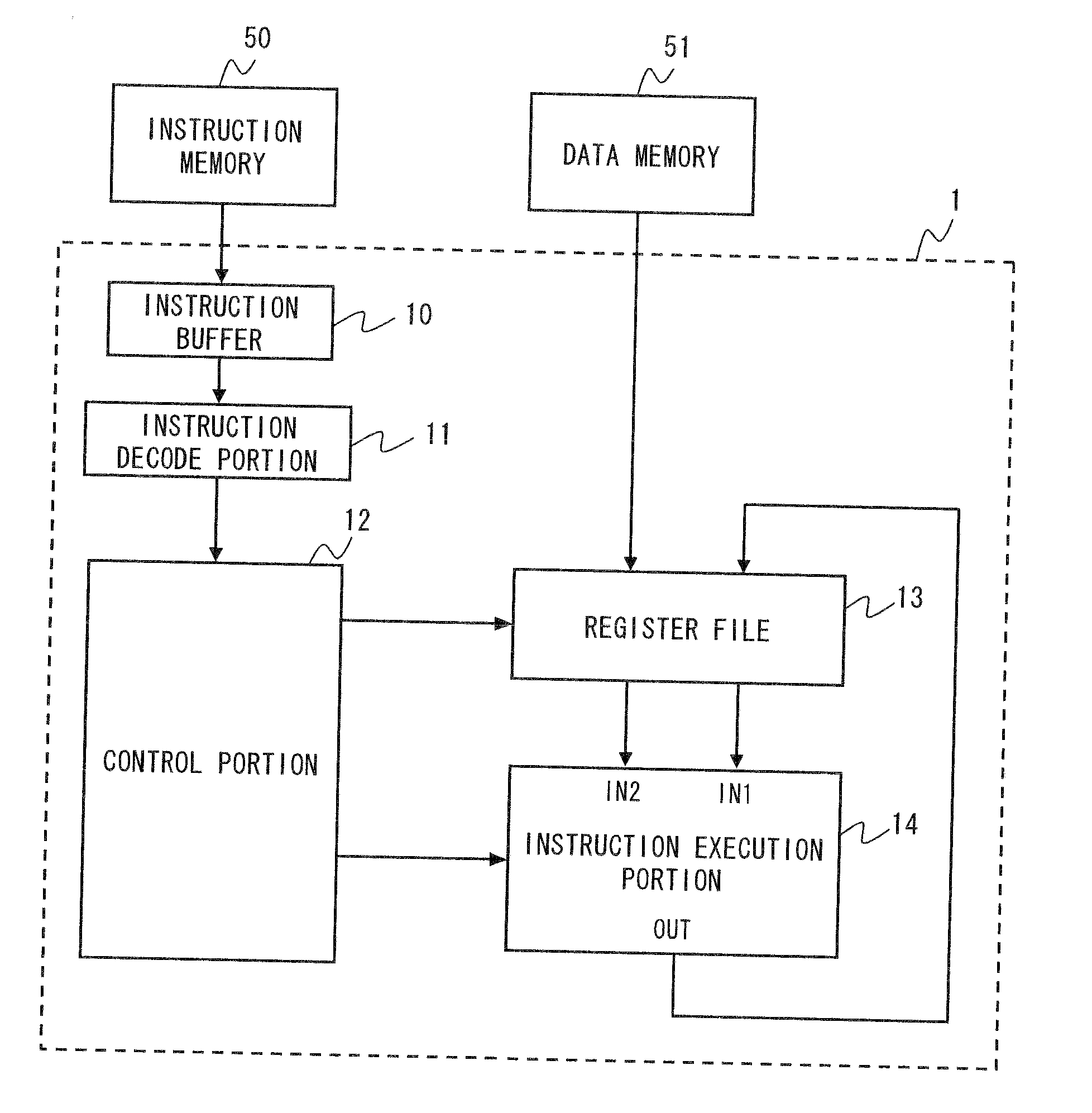
[0045]FIG. 1 shows a microprocessor 1 in accordance with this embodiment of the present invention. FIG. 1 is a block diagram illustrating an overall structure of the microprocessor 1. In FIG. 1, an instruction buffer 10 is a temporally storage area to store an instruction fetched from an instruction memory 50. An instruction decode portion 11 reads out an instruction stored in the instruction buffer 10, determines the instruction type of that instruction, and acquires the instruction operands of the instruction. A control portion 12 outputs either data or control signal, or both of them to a register file 13 and an instruction execution portion 14 based on the instruction type and instruction operands obtained by the instruction decoding.

[0046]The register file 13 includes a set of plural registers. In this embodiment, the following explanations are made with an assumption that the register file 13 has at least five registers R0-R5. Furthermore, assume that each register in the regi...

second embodiment

[0085]FIG. 10 shows the structure of a microprocessor 2 in accordance with this embodiment of the present invention. In comparison with the above-described microprocessor 1, the structure of the complex operation units contained in the instruction execution portion 24 of the microprocessor 2 is different from that of the instruction execution portion 14. Furthermore, the microprocessor 2 has a data select circuit 26 arranged between the output of the instruction execution portion 24 and the register file 13. The operation of the data select circuit 26 is controlled by a control portion 22.

[0086]As shown in FIG. 11, the instruction execution portion 24 has at least two complex operation units 240 and 250. FIG. 12 shows a configuration example of the complex operation unit 240. Incidentally, the complex operation unit 250 may have an identical structure with the complex operation unit 240. In the configuration example of the complex operation unit 240 in FIG. 12, the second MADD opera...


PUM


Abstract

A microprocessor has an instruction decode portion, a register file, a complex operation unit, and a data storage position determining mechanism. The complex operation unit performs complex operation, including complex multiplication, using first and second complex number data supplied from the register file based on an instruction decoded by the instruction decode portion, and outputs the result of the complex operation toward the register file. Furthermore, the data storage position determining mechanism determines the storage positions of the real part and imaginary part of output data of the complex operation unit in the register file such that the storage order of the real part and imaginary part of the output data in the register file is consistent with the storage orders of the real parts and imaginary parts of the first and second complex number data.

Description

BACKGROUND OF THE INVENTION[0001]1. Field of the Invention[0002]The present invention relates to a microprocessor that performs complex operations including complex multiplications such as Fast Fourier transform (FFT) and Inverse Fast Fourier Transform (IFFT).[0003]2. Description of Related Art[0004]There have been various proposals to make microprocessors perform FET calculations and IFFT calculations efficiently. For example, an online manual titled “Complex Fixed-Point Fast Fourier Transform Optimization for AltiVec™” publicized by Freescale Semiconductor, Inc. on the Internet (URL: http: / / www.freescale.com / files / 32bit / doc / app_note / AN2114.pdf) discloses an example of programs to cause a processor, adopting SIMD (Single Instruction Multiple Data) architecture capable of carrying out batch processing of 128-bit data, to perform Decimation In Frequency (DIF) type FFT calculations.[0005]Furthermore, Japanese Patent Translation Publication No. 2002-527808 discloses a technique in whic...

Claims


Application Information

Patent Timeline
IPC IPC(8): G06F17/10
CPCG06F7/4812G06F9/3885G06F9/30014G06F17/142
Inventor MATSUYAMA, HIDEKIDAITOU, MASAYUKI
Owner RENESAS ELECTRONICS CORP
Why Eureka
Try Eureka