Actuating device, bypass air bleed system equipped therewith, and turbojet engine comprising these

a technology of bypass air bleed and actuating device, which is applied in the direction of valve operating means/releasing devices, machines/engines, mechanical apparatuses, etc., can solve the problems of heavy and bulky ancillary systems, jack-operated actuating devices, etc., and achieve the effect of light weigh

Active Publication Date: 2009-03-05
SN DETUDE & DE CONSTR DE MOTEURS DAVIATION S N E C M A
View PDF11 Cites 22 Cited by
  • Summary
  • Abstract
  • Description
  • Claims
  • Application Information

AI Technical Summary

Benefits of technology

[0030]One advantage of the actuating system according to the invention lies in the fact that it is lighter in weight and more compact than the actuating devices of the known art which employ jacks and their ancillaries. It does not use high-pressure liquids that require special precautions, and neither does it employ electric power generators.

Problems solved by technology

Such jack-operated actuating devices have disadvantages.
All these ancillary systems are heavy and bulky.

Method used


Image

  • Actuating device, bypass air bleed system equipped therewith, and turbojet engine comprising these
  • Actuating device, bypass air bleed system equipped therewith, and turbojet engine comprising these
  • Actuating device, bypass air bleed system equipped therewith, and turbojet engine comprising these

Examples


first embodiment

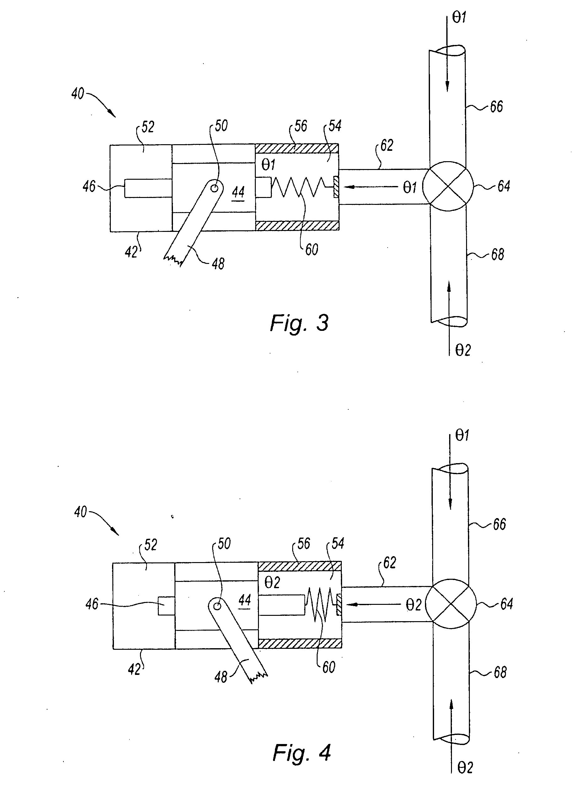
[0038]FIGS. 3 and 4 schematically illustrate how an actuating device 40 according to the invention works. The actuating device 40 comprises a casing 42 in which there is housed a mechanism 44 comprising a piston 46 capable of performing a translational movement between a first position illustrated in FIG. 3 and a second position illustrated in FIG. 4.

[0039]The mechanism 44 also comprises a crank 48 capable of rotating about an axle 50 between a first position illustrated in FIG. 3 and a second position illustrated in FIG. 4. The rotation of the crank 48 about the axle 50 is caused by the translational displacement of the piston 46, by means of an intermediate member such as, for example, a lever or a hydraulic piston which has not been depicted in FIGS. 3 and 4.

[0040]The casing 42 also has two housings 52, 54 positioned respectively one on each side of the mechanism 44. These two housings 52, 54 are each capable of housing part of the piston 46 during its translational movement. One...

second embodiment

[0051]FIGS. 5 and 6 schematically illustrate how an actuating device 40 according to the invention works.

[0052]The actuating device 40 comprises a casing 42 housing a mechanism 44 comprising a piston 46 able to perform a translational movement between a first position illustrated in FIG. 5 and a second position illustrated in FIG. 6. Just as in the first embodiment, the mechanism 44 comprises a crank 48 and an axle 50. The casing 42 has two housings 542, 544 positioned one on each side of the mechanism 44 and each capable of housing part of the piston 46 during its translational movement.

[0053]According to the second embodiment, each of these housings 542, 544 comprises thermal insulation means 56 so as to form two heat insulated 542, 544.

[0054]The actuating device 40 comprises two two-way shape memory alloy coil springs 602, 604 which actuate the piston 46 in its translational movement. Each coil spring 602, 604 has one end attached to that one of the two ends of the piston 46 whic...


PUM


Abstract

The actuating device for opening and closing at least one shutter in a gas turbine engine such as a turbojet engine, comprises at least one actuator made of a two-way shape memory alloy having a first stable state at a first given temperature (θ1, θ3) in which state it actuates either the opening or the closing of the shutter, and a second stable state at a second given temperature (θ2, θ4), in which state it actuates either the closing or the opening of the shutter, respectively.

Description

BACKGROUND OF THE INVENTION[0001]The present invention relates to the field of gas turbine engines and more particularly to that of bypass turbojet engines.[0002]It relates more specifically to a device for actuating a shutter in a turbojet engine, to a bypass air bleed system equipped with such an actuating device, and to a turbojet engine comprising these.[0003]An aircraft bypass turbojet engine comprises, as is known, a primary gas flow duct and a secondary gas flow duct, which ducts are separated by an inter-duct compartment of an intermediate casing. Positioned in the primary duct, from the upstream direction downstream with respect to the direction in which the gases flow, are a low-pressure compressor and a high-pressure compressor. The air thus compressed is conveyed to a combustion chamber in which it is mixed with pressurized fuel which is burnt to provide, downstream of the combustion chamber, energy to a high-pressure turbine which drives the high-pressure compressor and...

Claims


Application Information

Patent Timeline
Patent Type & Authority Applications(United States)
IPC IPC(8): F02K3/02
CPCF01D17/14F01D17/141Y02T50/671F02C9/18F02C6/08F04D27/0215F04D27/023F05D2300/505Y02T50/60
Inventor MONS, CLAUDE MARCEL
Owner SN DETUDE & DE CONSTR DE MOTEURS DAVIATION S N E C M A
Why Eureka
Try Eureka