
Acoustic Side Cover for an Engine

a side cover and engine technology, applied in the direction of machines/engines, mechanical equipment, combustion air/fuel air treatment, etc., can solve the problems of engine noise, engine noise is substantial, and the combustion noise level of acoustically treated engines is higher, so as to reduce the overall mass and reduce the noise of the engine. , the effect of increasing fuel economy

Inactive Publication Date: 2009-03-05
GM GLOBAL TECH OPERATIONS LLC
View PDF7 Cites 11 Cited by
  • Summary
  • Abstract
  • Description
  • Claims
  • Application Information

AI Technical Summary

Benefits of technology

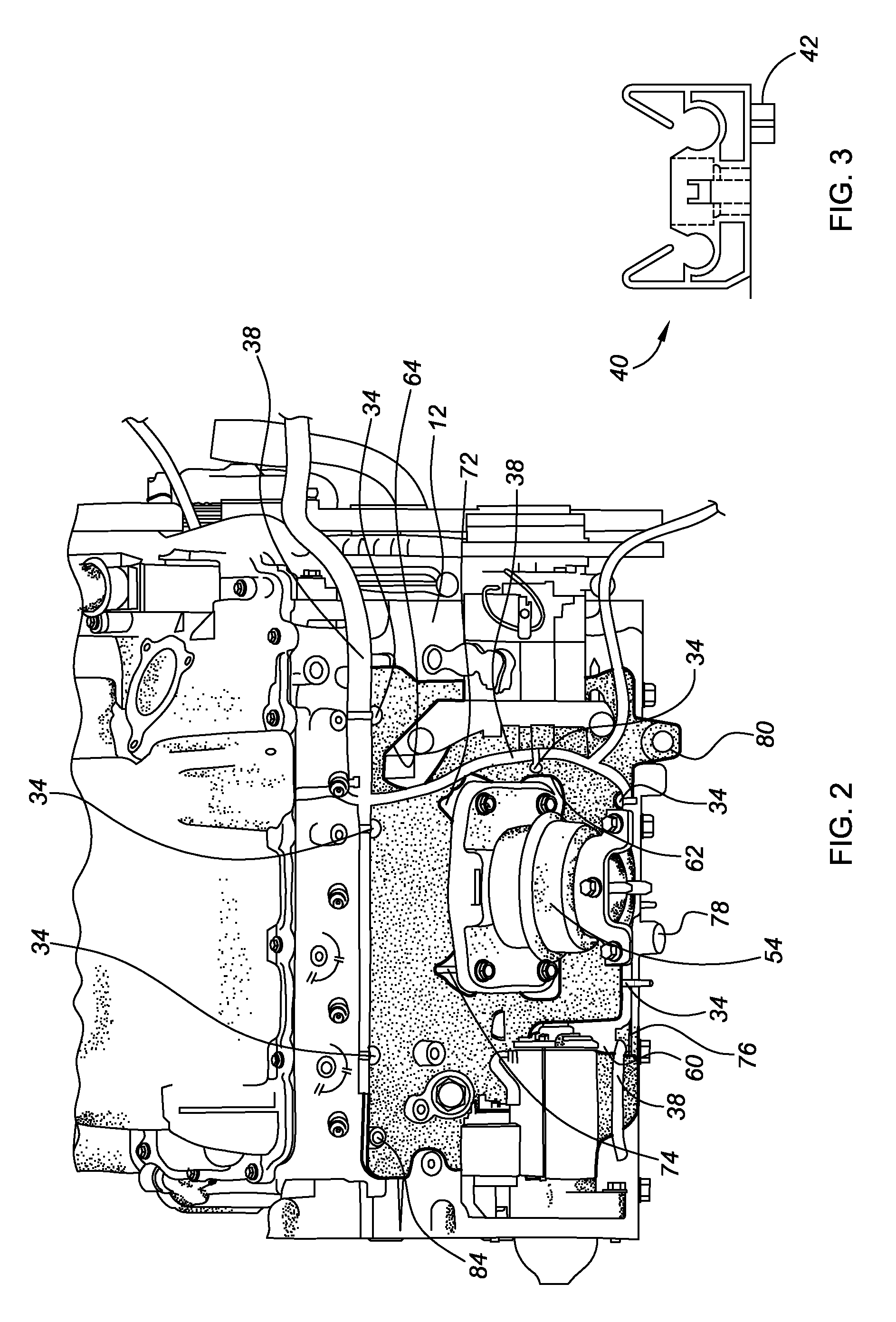
[0004]An apparatus for reducing engine noise includes a side cover configured to operatively connect to a side of an engine block. The cover has a first layer configured to be adjacent to the engine block. The first layer is made of a first acoustic-absorbing material. The cover also has a second layer configured to be adjacent to the first layer opposite the engine block. The second layer is a second substantially rigid material that acts as an acoustic barrier and is configured to operatively support at least one engine component such as an electrical or fluid line. The second layer may have an integrally-formed fastener or channel used to provide such support. By configuring the side cover to support engine components, the engine block may not require as many bosses that are typically used for mounting brackets for hoses, wiring harnesses, etc. Overall mass is thus reduced, with an associated increase in fuel economy, as the side cover is less dense than a boss formed by the engine block.

Problems solved by technology

Engines generate a substantial amount of noise.
For example, diesel engines can be especially loud during a cold start.
Additionally, an acoustically-treated engine may have higher combustion noise levels to improve fuel economy, emissions, power and torque, while still maintaining pleasing NVH (noise, vibration and harshness) characteristics.

Method used


Image

  • Acoustic Side Cover for an Engine
  • Acoustic Side Cover for an Engine
  • Acoustic Side Cover for an Engine

Examples


Embodiment Construction

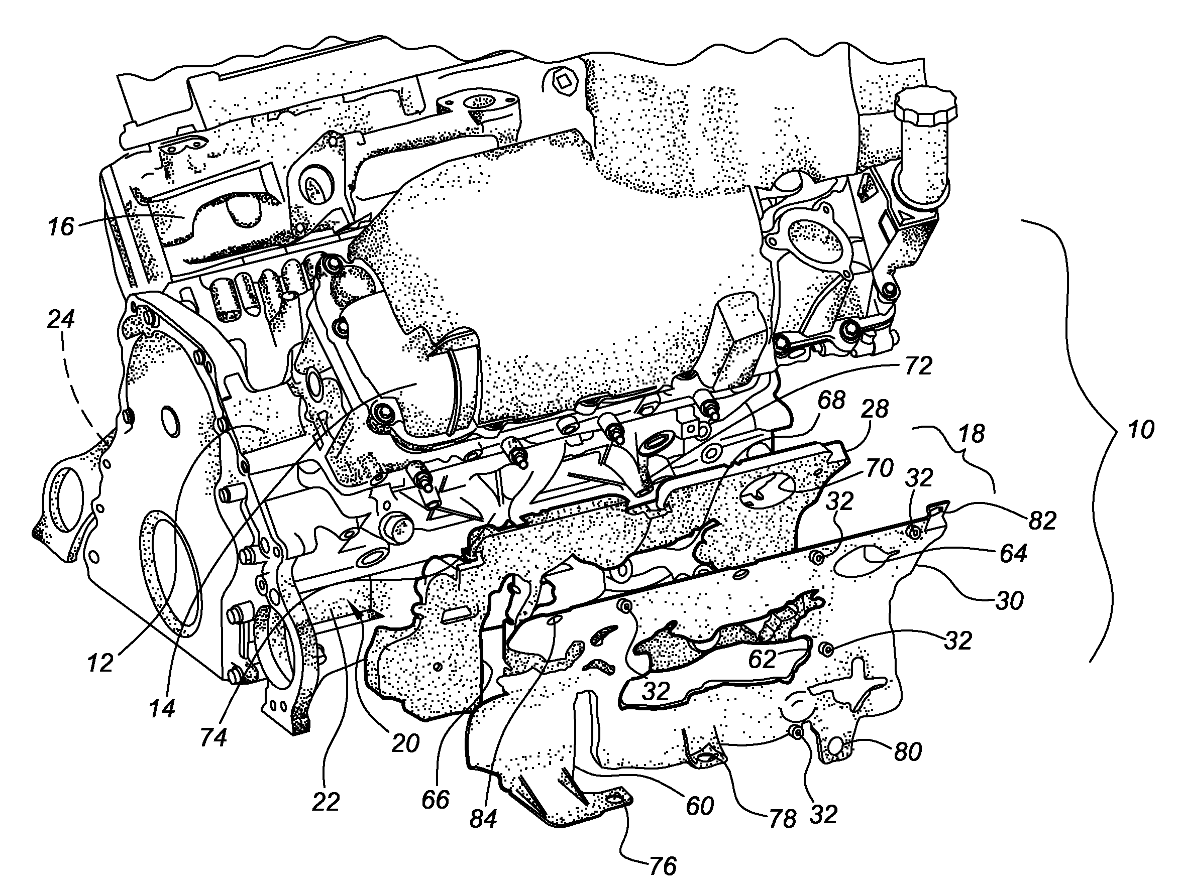
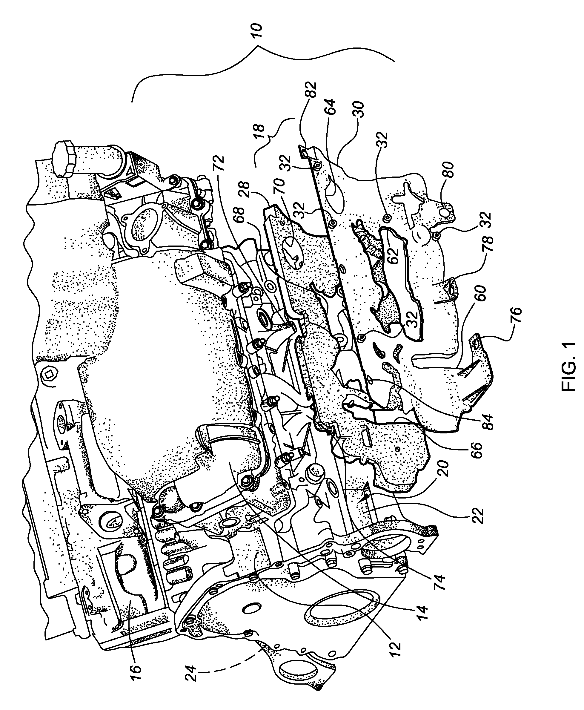
[0011]Referring to the drawings, wherein like reference numbers refer to like components, FIG. 1 shows a V-8 diesel engine 10 having an engine block 12 that defines two opposing rows of cylinder bores (not visible, but well understood by those skilled in the art), slanting inward from beneath cylinder head covers 14, 16, as is well understood by those skilled in the art. It should be understood that other types of engines may be used within the scope of the invention as well. However, diesel engines may especially benefit from the noise reduction function of the side covers 18 described herein.

[0012]A first side cover 18 is shown in exploded view adjacent an outer surface 20 of a side 22 of the engine block 12. A substantially similar second side cover (not shown) is operatively connected to a second side 24 (indicated in phantom) of the engine block 12. The side cover 18 has a first or inner layer 28 formed from an acoustic-absorbing material such as, but not limited to, polyuretha...


PUM


Abstract

An apparatus for reducing engine noise includes a side cover configured to operatively connect to a side of an engine block. The side cover has a first layer configured to be adjacent to an outer surface of the side of the engine block. The first layer is made of a first acoustic-absorbing material. The side cover also has a second layer configured to be adjacent to the first layer opposite the engine block. The second layer is a second substantially rigid material establishing an acoustic barrier and is configured to operatively support at least one engine component such as an electrical or fluid line, such as by an integrally formed fastener or channel.

Description

CROSS-REFERENCE TO RELATED APPLICATIONS[0001]This application claims the benefit of U.S. Provisional Application No. 60 / 970,010, filed Sep. 5, 2007, which is hereby incorporated by reference in its entirety.TECHNICAL FIELD[0002]The invention relates to a side cover for an engine providing an acoustic barrier.BACKGROUND OF THE INVENTION[0003]Engines generate a substantial amount of noise. For example, diesel engines can be especially loud during a cold start. Minimizing engine noise helps to create a more pleasant driving experience. Additionally, an acoustically-treated engine may have higher combustion noise levels to improve fuel economy, emissions, power and torque, while still maintaining pleasing NVH (noise, vibration and harshness) characteristics. Any noise reduction strategy should be balanced against the increased cost and the potential reduction in fuel economy associated with added components, their additional mass, and any additional processing and assembly steps.SUMMARY...

Claims


Application Information

Patent Timeline
Patent Type & Authority Applications(United States)
IPC IPC(8): F02B77/13E04B1/82
CPCF02F7/0068F02B77/13
Inventor HAZELTON, GARY J.
Owner GM GLOBAL TECH OPERATIONS LLC
Learn More