Hold-down device for a fuel injection device, and fuel injection device

a technology of fuel injection device and hold-down device, which is applied in the direction of fuel injection apparatus, machine/engine, feed system, etc., can solve the problems of enlargement of the radial extension of the fuel, changes in the stroke, and the twisting effect of the various holding parts on the fuel injection valve, so as to achieve easy and economical manufacture and simple construction.

Active Publication Date: 2009-03-05
ROBERT BOSCH GMBH
View PDF17 Cites 38 Cited by
  • Summary
  • Abstract
  • Description
  • Claims
  • Application Information

AI Technical Summary

Benefits of technology

[0005]The hold-down device according to the present invention for a fuel injection device has the advantage that it has a particularly simple construction, is very easy and economical to manufacture, and nonetheless achieves a very effective holding down of a fuel injection valve in a receptacle bore of a cylinder head or of an intake pipe. Using conventional manufacturing methods, such as stamping, eroding, or laser cutting, blanks for the eventual hold-down device can be detached from sheets of spring steel or high-grade steel, and can be brought into numerous fairly complex desired shapes through bending.
[0007]It is advantageous to realize the hold-down device as a stamped bent part, and to shape it and to install it in a fuel injection device in such a way that the surfaces of the oblique segments and support segments of the hold-down device that are loaded by bending tension run perpendicular to the cut edges that result when the blank for the hold-down device is detached from the corresponding sheet. In this way, the long-term loading capacity of the segments, loaded to the point of bending, of the hold-down clip of the hold-down device can be increased, and an optimal hold-down force, exerted on the fuel injection valve so as to fix it securely in the receptacle bore, can be achieved.
[0008]The fuel injection device according to the present invention, has the advantage that, through simple measures at the fuel injection valve and at the connecting fitting, a direct and therefore very precise rotational fixing is created between the fuel injection valve and the connecting fitting. For this purpose, on the fuel injection valve a pin-shaped raised cog is provided that corresponds to a groove-type recess or opening on the connecting fitting of the fuel distributor line. The cog, extending into the opening, of the fuel injection valve provides, independent of the hold-down device, a rotational securing of the fuel injection valve in relation to the fuel distributor line, and provides a secure allocation of the rotational position of the hold-down device to the fuel injection valve.

Problems solved by technology

A disadvantage of the fastening device known from German Patent Publication No. 29 26 490 is in particular the twisting effect that the various holding parts have on the fuel injection valve.
The flow of force that is produced in the fuel injection valve results in deformations, and thus in changes in the stroke of the valve needle, up to the point of jamming, and to a pressure or bending load on the housing parts, which in general have thin walls and are welded to one another at various points.
In addition, each fastening measure, using for example a bearing collar, results in an enlargement of the radial extension of the fuel injection valve, and thus to an increased space requirement during installation.
Due to its tubular structure, the sleeve can transmit the hold-down forces to the fuel injection valve with only limited effectiveness.

Method used


Image

  • Hold-down device for a fuel injection device, and fuel injection device
  • Hold-down device for a fuel injection device, and fuel injection device
  • Hold-down device for a fuel injection device, and fuel injection device

Examples


Embodiment Construction

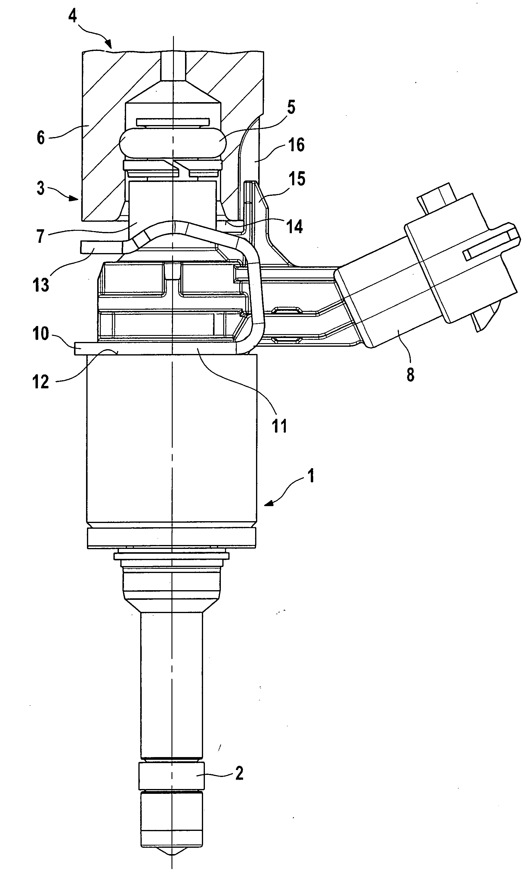
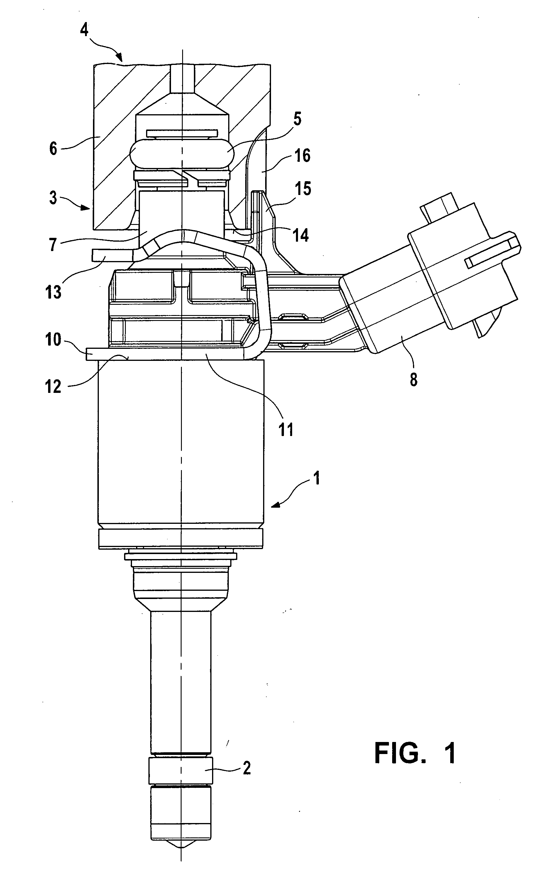
[0017]In FIG. 1, as an exemplary embodiment a valve is shown in the form of an injection valve 1 for fuel injection systems of mixture-compressing externally ignited internal combustion engines, in a side view. Fuel injection valve 1 is part of a fuel injection device. With a downstream end, fuel injection valve 1, realized in the form of a direct-injecting injection valve for the direct injection of fuel into a combustion chamber of the internal combustion engine, is installed in a receptacle bore of a cylinder head (not shown). A sealing ring 2, made in particular of Teflon, provides an optimal sealing of fuel injection valve 1 in relation to the wall of the cylinder head. The valve receptacle can likewise be provided on a receptacle fitting of an intake pipe (not shown).

[0018]On its end 3 at the inflow side, fuel injection valve 1 has a plug connection to a fuel distributor line 4, sealed by a sealing ring 5 between a connecting fitting 6 of fuel distributor line 4, shown in sect...


PUM


Abstract

The hold-down device for a fuel injection device is distinguished by a particularly simple design that nonetheless permits a very effective holding down of a fuel injection valve. The fuel injection device includes at least one fuel injection valve, a receptacle bore for the fuel injection valve, and a connecting fitting of a fuel distributor line, the hold-down device being clamped between a shoulder of the fuel injection valve and an end surface of the connecting fitting. The hold-down device has a partially annular base element from which there extends, in a bent-away fashion, an axially flexible hold-down clip that has at least two webs, two oblique segments, and two support segments. The fuel injection valve is particularly suitable for use in fuel injection systems of mixture-compressing externally ignited internal combustion engines.

Description

FIELD OF THE INVENTION[0001]The present invention is based on a hold-down device for a fuel injection device, as well as to a fuel injection device.BACKGROUND INFORMATION[0002]From German Patent Publication No. 29 26 490, a fastening device is known for fastening a fuel injection valve to an intake pipe, in which the axial fixing of the fuel injection valve to the fuel distributor line, or to a plug nipple, takes place via a fastening element constructed as a U-shaped securing bracket having two limbs that are flexible in the radial direction. In the assembled state, the securing bracket engages through corresponding openings in the plug nipple, and is capable of snapping into an opening, fashioned as an annular groove, in a connecting fitting of the fuel injection valve. The axial play between the openings and the securing bracket, as well as between the annular groove and the securing bracket, should be kept small in order to achieve a precise fixing of the fuel injection valve wi...

Claims


Application Information

Patent Timeline
Patent Type & Authority Applications(United States)
IPC IPC(8): F02M61/14
CPCF02M61/14F02M2200/856F02M2200/8023
Inventor FURST, THOMASBOLZ, THILO
Owner ROBERT BOSCH GMBH
Why Eureka
Try Eureka