Eureka AIR delivers breakthrough ideas for toughest innovation challenges, trusted by R&D personnel around the world.

Fuel dispensing nozzle inhibitor

Inactive Publication Date: 2009-03-05
INERGY AUTOMOTIVE SYST RES (SA)
View PDF15 Cites 5 Cited by
  • Summary
  • Abstract
  • Description
  • Claims
  • Application Information

AI Technical Summary

Benefits of technology

[0008]When an unsuitable delivery nozzle is inserted into the filler pipe, the valve mounted in the head of the filler pipe prevents the insertion of the unsuitable delivery nozzle by interaction of the stop device with the free end of the delivery nozzle. This interaction stops the valve from swinging into its open position and prevents the delivery nozzle from being inserted into the filler pipe.
[0030]It should be noted that according to the invention, the valve is the one closing off tightly the capless filler pipe head. Such a closure valve is configured so as to prevent in its closed position, liquid fuel or fuel vapour leaking into the atmosphere.

Problems solved by technology

The use of a fuel unsuitable for the engine generally has an undesirable, or even disastrous, effect on the engine.
A filling error quickly arises and may for example be caused by a lack of knowledge of the vehicle in question or by lack of attention.
This risk is higher if the user is not the regular user of the vehicle, for example in the case of hire cars.
Thus, diesel delivery nozzles, which have a larger diameter than the filler pipes of petrol tanks, cannot be inserted into the filler pipe of a petrol tank.
However, the contrary is not true.
Currently, there are no systems for preventing a diesel tank from being filled with petrol.
In the event of such a cap being lost, the passage between the fuel tank and atmosphere remains open and contamination of the atmosphere by liquid fuel or fuel vapour cannot be avoided.
However, such a closure valve does not prevent petrol from being poured into a diesel tank.

Method used


Image

  • Fuel dispensing nozzle inhibitor
  • Fuel dispensing nozzle inhibitor
  • Fuel dispensing nozzle inhibitor

Examples


first embodiment

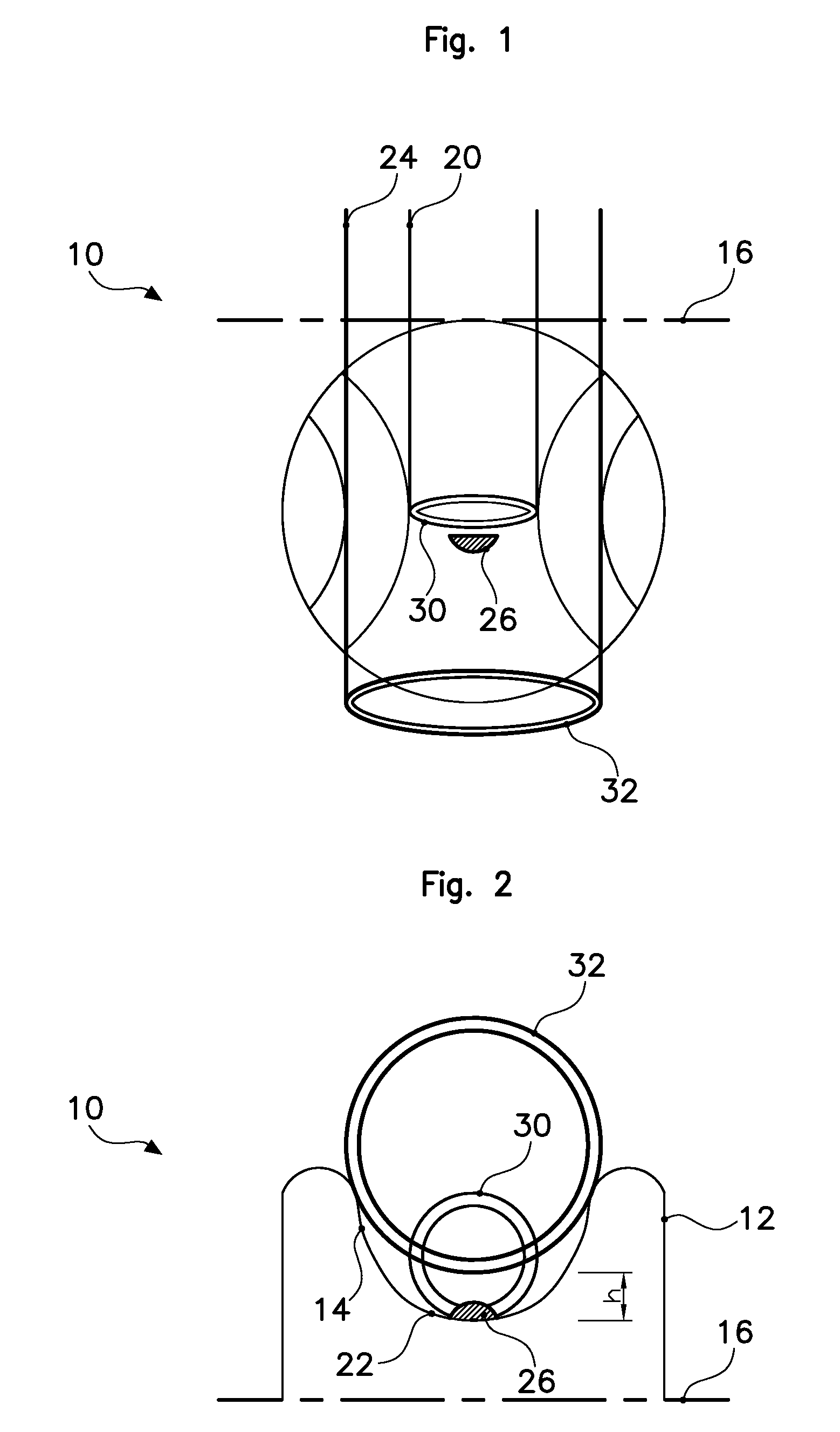
[0038]a valve according to the invention is illustrated in FIGS. 1 and 2. Such a valve 10 includes a cover 12 with a guiding groove 14 extending essentially perpendicular to the swing axis 16 of the valve 10.

[0039]The guiding groove 14 is dimensioned so as to receive a petrol delivery nozzle 20 on its bottom 22 and to receive a diesel delivery nozzle 24 at a predetermined distance h from the bottom 22. A stop catch 26 having a height of less than the predetermined distance h is provided in the bottom 22 of the guiding groove 14 so that, when a petrol delivery nozzle 20 is inserted into a filler pipe head, the free end 30 of the petrol delivery nozzle 20 exerts a force on the valve 10 and makes it swing about the swing axis 16 into an open position. When the valve 10 has swung open, the free end 30 of the petrol delivery nozzle 20 is guided by the guiding groove 14. When the free end 30 of the petrol delivery nozzle 20, which is received on the bottom 22 of the guiding groove 14, com...

second embodiment

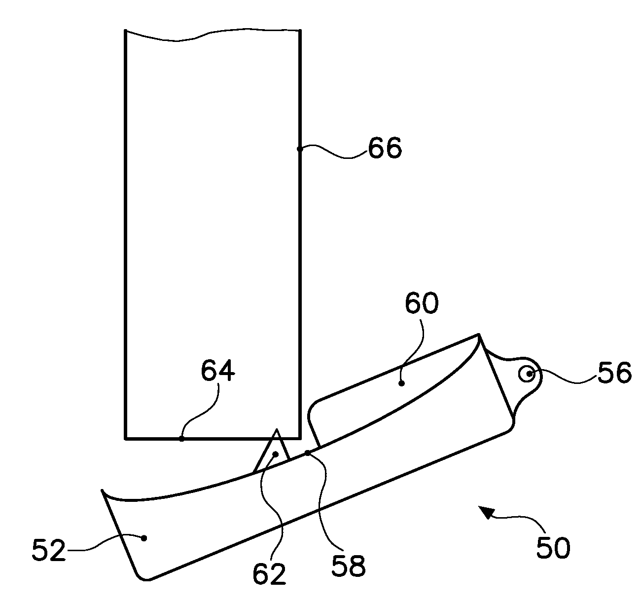
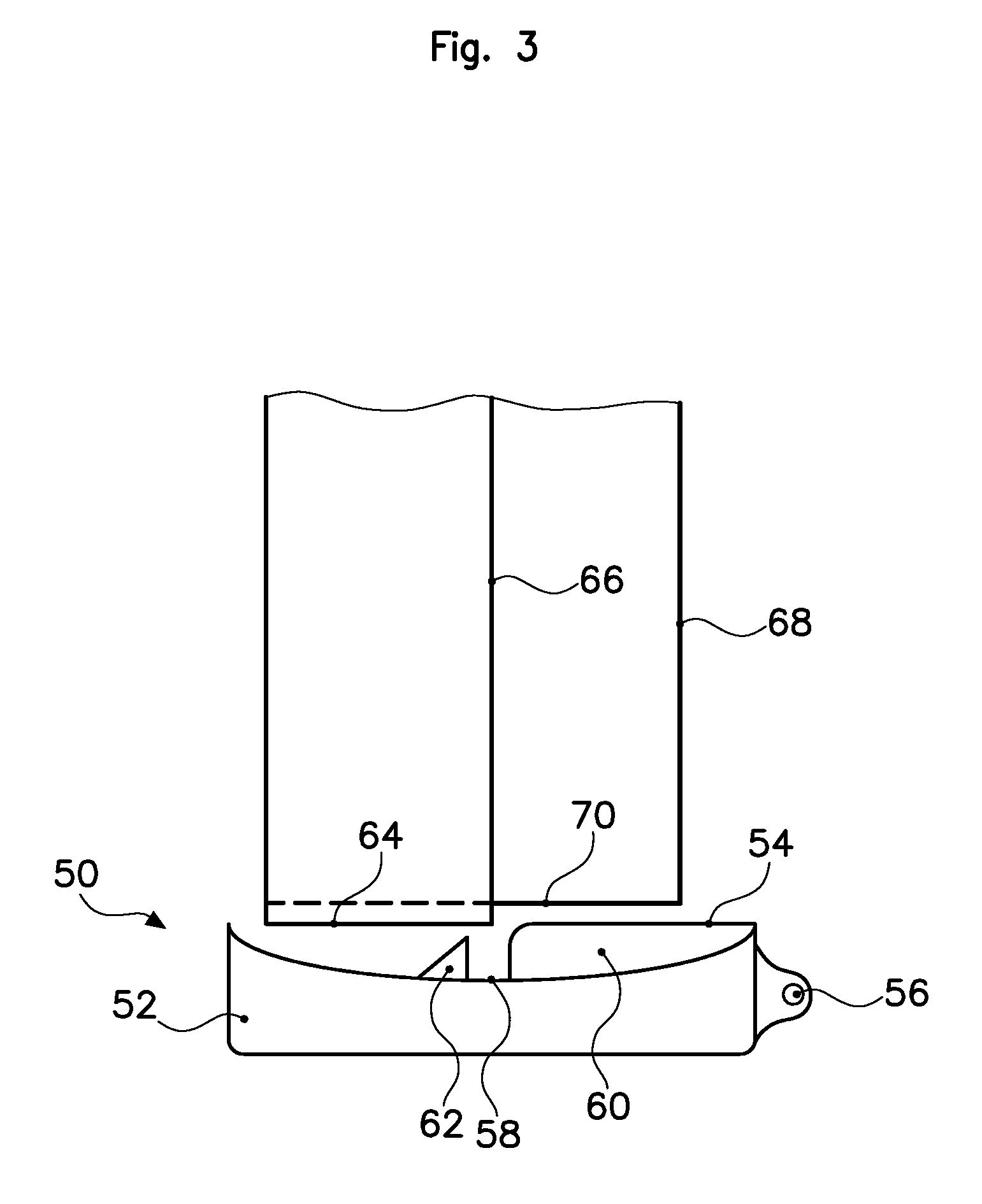
[0041]a valve according to the invention is illustrated in FIGS. 3, 4 and 5. Such a valve 50 includes a cover 52 with a projection 54 extending radially between the swing axis 56 and the centre of the valve 50. The projection 54 includes a recess 58 dividing the projection radially into a first portion 60 and a second portion 62, preferably in the form of a triangle. The recess 58 is dimensioned and designed so as to receive the free end 64 of a petrol delivery nozzle 66.

[0042]When a petrol delivery nozzle 66 is inserted, as illustrated in FIG. 4, the free end 64 is received in the recess 58 of the projection 54, between the first portion 60 and the second portion 62. When the nozzle 66 is inserted further into the pipe, the swinging of the valve 50 allows the free end 64 of the nozzle 66 to come into contact with the second portion 62, which then acts as a stop catch and prevents the petrol delivery nozzle 66 from being inserted into the filler pipe and prevents the valve 50 from s...


PUM

PropertyMeasurementUnit
Forceaaaaaaaaaa
Diameteraaaaaaaaaa
Heightaaaaaaaaaa

Abstract

Safety system for a filter pipe for filling a tank, in particular a fuel tank, the filler pipe including a pipe head suitable for receiving a delivery nozzle, the system including a valve which is mounted in the pipe head and is able to swing, between closed and open positions, about a swing axis essentially tangential to the periphery of the valve. The valve is kept closed outside the filling periods by a prestressing means and is swung open by a force exerted by a free end of the delivery nozzle against a contact face of the valve during the nozzle insertion into the filler pipe. In some embodiments, the valve is for closing off tightly a capless filler pipe, and includes, on its contact face, a stop device designed to allow the insertion of a suitable delivery nozzle into the filler pipe, and not of an unsuitable nozzle.

Description

CROSS-REFERENCE TO RELATED APPLICATIONS[0001]This application is a U.S. national stage application under 35 U.S.C. §371 of International Application No. PCT / EP2007 / 052356, filed Mar. 13, 2007, which claims priority to French Application No. 06.02265 filed Mar. 15, 2006, and to French Application No. 06.07315, filed Aug. 11, 2006, all of these applications being herein incorporated by reference in their entirety for all purposes.FIELD OF THE INVENTION[0002]The present invention relates to a safety system for a filler pipe, for filling a tank, in particular a fuel tank. The invention relates especially to a safety system for preventing the insertion of an unsuitable delivery nozzle into the filler pipe.BACKGROUND OF THE INVENTION[0003]In a motor vehicle, the fuel used to operate the engine is, in most cases, petrol or diesel. The use of a fuel unsuitable for the engine generally has an undesirable, or even disastrous, effect on the engine. When filling the tank with fuel, the user or ...

Claims


Application Information

Patent Timeline
IPC IPC(8): B60K15/04
CPCB60K15/04B60K2015/0483B60K15/0406B60K15/05
Inventor JOURNEE, MAURICE
Owner INERGY AUTOMOTIVE SYST RES (SA)
Why Eureka
Eureka Blog
Learn More