Diffusion layer for pressure vessels

a pressure vessel and diffusion layer technology, applied in the field of hollow vessels, to achieve the effect of facilitating the flow of fluid

Active Publication Date: 2009-03-05
GM GLOBAL TECH OPERATIONS LLC
View PDF5 Cites 65 Cited by
  • Summary
  • Abstract
  • Description
  • Claims
  • Application Information

AI Technical Summary

Benefits of technology

[0007]In another embodiment, the vessel comprises a hollow inner shell formed from a moldable material and adapted to store a fluid; a boss adhered to the moldable material of said inner shell and forming a substantially fluid tight seal therebetween; a diffusion layer formed around at least a portion of said inner shell, wherein said diffusion layer facilitates the flow of a fluid from the diffusion layer to an exterior of said vessel; and an outer shell formed around said diffusion layer and said inner shell.
[0008]In another embodiment, the vessel comprises a hollow inner shell formed from a moldable material and adapted to store a fluid; a boss adhered to the moldable material of said inner shell and forming a substantially fluid tight seal therebetween, wherein said boss includes a flow channel formed therein in fluid communication with an exterior of said vessel and the diffusion layer; a diffusion layer formed around at least part of said inner shell, wherein said diffusion layer facilitates the flow of a fluid from the diffusion layer, through said boss, and to the exterior of said vessel; and an outer shell formed around said diffusion layer and said inner shell.

Problems solved by technology

The filament winding process often results in the creation of a space between the outer shell and the inner shell of the fuel tank.

Method used


Image

  • Diffusion layer for pressure vessels
  • Diffusion layer for pressure vessels
  • Diffusion layer for pressure vessels

Examples


Embodiment Construction

[0013]The following detailed description and appended drawings describe and illustrate various exemplary embodiments of the invention. The description and drawings serve to enable one skilled in the art to make and use the invention, and are not intended to limit the scope of the invention in any manner. In respect of the methods disclosed, the steps presented are exemplary in nature, and thus, the order of the steps is not necessary or critical.

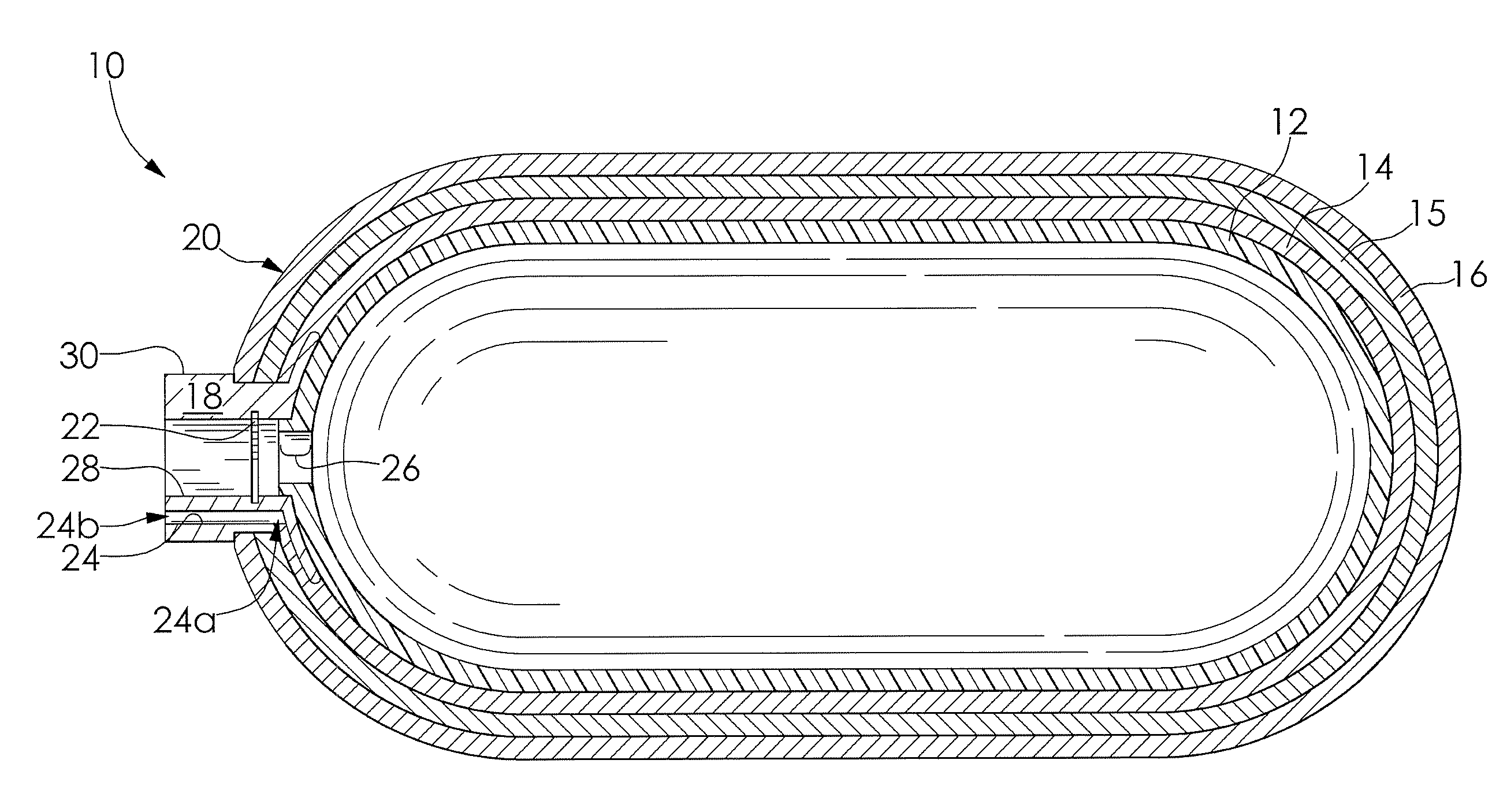
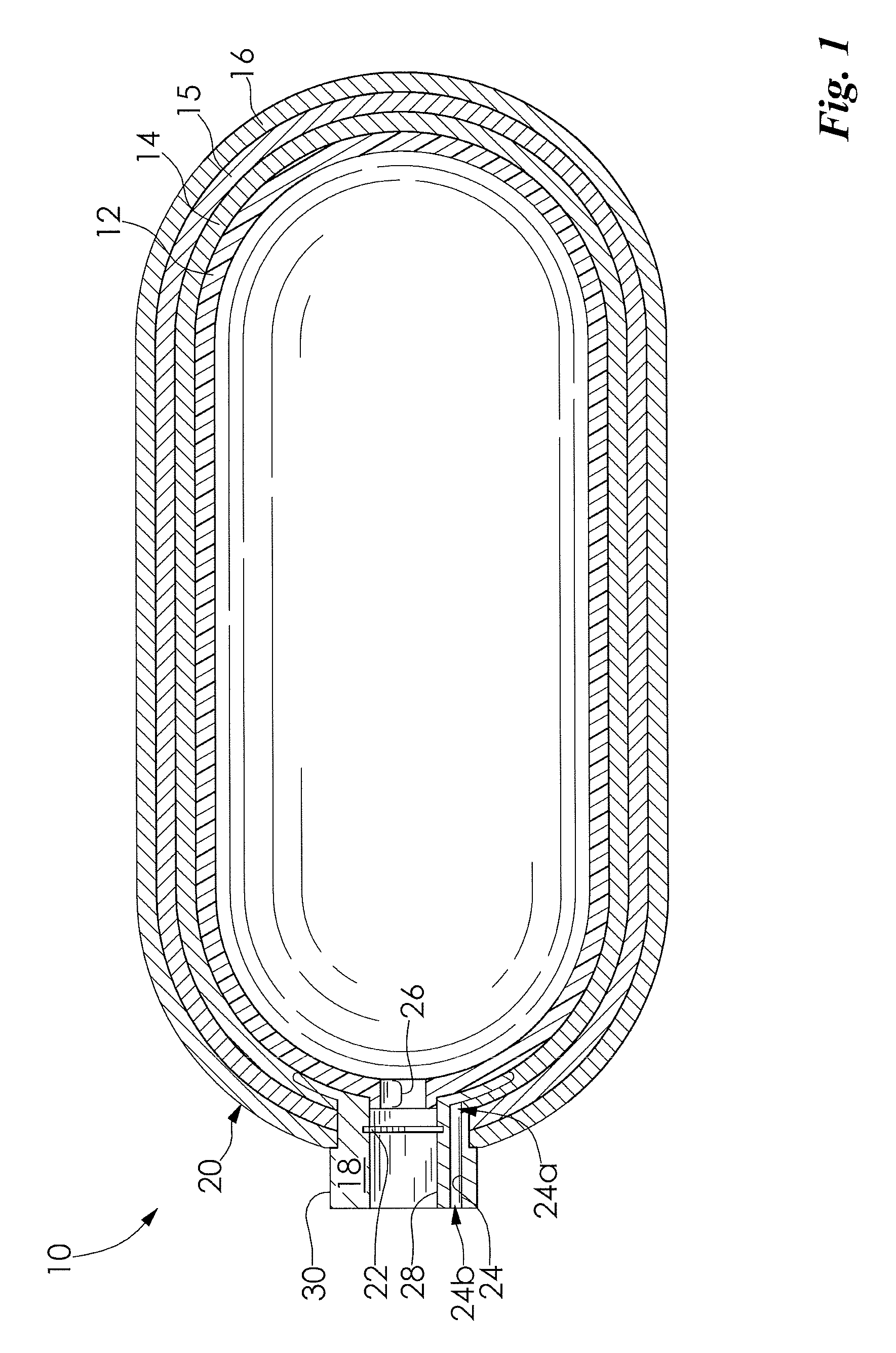
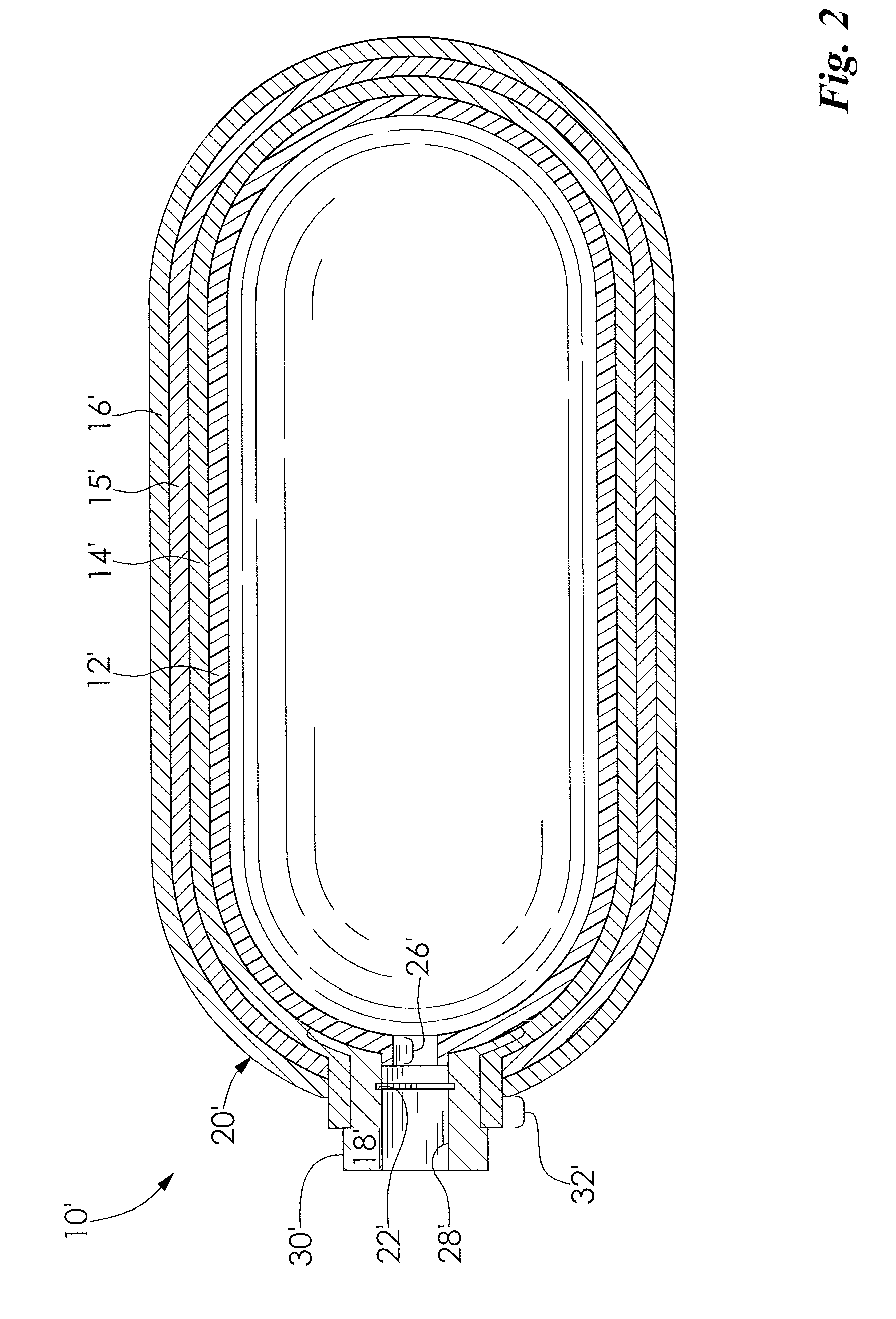
[0014]FIG. 1 illustrates a hollow pressure vessel 10 having an inner shell 12, a diffusion layer 14, and an outer shell 16. The vessel 10 has a substantially cylindrical shape and is adapted to hold a pressurized fluid (not shown). It is understood that the vessel 10 may have any shape as desired. The pressurized fluid may be any fluid such as a gas such as hydrogen gas and oxygen gas, a liquid, and both a liquid and a gas, for example.

[0015]The vessel 10 includes a boss 18 disposed on a first end 20 thereof. The boss 18 is a separately prod...


PUM

PropertyMeasurementUnit
moldableaaaaaaaaaa
cylindrical shapeaaaaaaaaaa
shapeaaaaaaaaaa

Abstract

Disclosed is a vessel and a method of forming the vessel including an inner shell, an outer shell, and a diffusion layer disposed therebetween, wherein the diffusion layer facilitates the venting of a fluid from between the inner shell and the outer shell.

Description

FIELD OF THE INVENTION[0001]The invention relates to a hollow vessel and more particularly to a method and apparatus for forming a hollow pressure vessel having an inner shell, an outer shell, and a diffusion layer disposed therebetween, wherein the diffusion layer facilitates a venting of a fluid that has penetrated the inner shell.BACKGROUND OF THE INVENTION[0002]Fuel cells have been proposed as a power source for electric vehicles and other applications. In proton exchange membrane (PEM) type fuel cells, hydrogen is supplied as a fuel to an anode of the fuel cell and oxygen is supplied as an oxidant to a cathode of the fuel cell. A plurality of fuel cells is stacked together in fuel cell stacks to form a fuel cell system. The fuel and oxidant are typically stored in large pressurized hollow vessels, such as fuel tanks, disposed on an undercarriage of the vehicle.[0003]The pressurized vessels may be multi-layered and include at least an inner shell and an outer shell. Some inner s...

Claims


Application Information

Patent Timeline
Patent Type & Authority Applications(United States)
IPC IPC(8): F17C1/02
CPCB29C41/04Y02E60/321B29C49/04B29C70/086B29C70/32B29C70/86B29D22/003B29L2009/00B29L2031/7156B29L2031/7172F17C1/06F17C2201/0109F17C2201/054F17C2201/056F17C2203/0604F17C2203/0621F17C2203/0636F17C2203/0646F17C2203/0648F17C2203/0658F17C2203/066F17C2203/0663F17C2203/0697F17C2205/0305F17C2209/2127F17C2209/2145F17C2209/2163F17C2221/011F17C2221/012F17C2223/0123F17C2223/013F17C2223/0146F17C2223/036F17C2260/037F17C2270/0168F17C2270/0184B29C41/22Y02E60/32
Inventor SCHLAG, HARALD
Owner GM GLOBAL TECH OPERATIONS LLC
Why Eureka
Try Eureka