Beverage dispensing system with a head capable of dispensing plural different beverages

a beverage dispensing system and beverage technology, applied in liquid transferring devices, instruments, liquid handling, etc., can solve the problems of significant space reduction, significant space reduction, and limited design of known dispensing heads, so as to reduce the carbonation breakout, reduce the pressure of one or more base components, and be convenient to assemble.

Active Publication Date: 2009-03-05
PEPSICO INC
View PDF29 Cites 0 Cited by
  • Summary
  • Abstract
  • Description
  • Claims
  • Application Information

AI Technical Summary

Benefits of technology

[0013]Still another feature of this invention is that it makes it possible to simultaneously discharge, from a single dispensing head, different blends of concentrate. For example, the single dispensing head of this invention can discharge a pure concentrate of a soda or the soda concentrate and a second, supplemental flavor concentrate. Thus, the single dispensing head of this invention discharges flavored beverages that are combinations of concentrates.
[0015]It is another feature of the present invention to provide for a more elegant, simpler to assemble, improved method for gradually reducing the pressurization of one or more base components, for example, carbonated water, while minimizing the carbonation breakout.
[0016]A further feature of this invention is to provide a dispensing head that is easy to remove from, and reinstall to, the base unit with which it is associated and that the removal of the dispensing head does not cause leakage of the beverage forming ingredients.
[0017]An additional feature of the dispensing system of this invention is that, after installation, the system can supply beverages formed from combinations of one or more different liquids without having to extensively reconfigure the system's internal fluid supply lines.

Problems solved by technology

However, there is a limitation associated with the design of known dispensing heads.
These multi-headed dispensing units occupy a significant amount of counter space.
At some establishments, providing counter space needed for large-sized dispensing units significantly reduces space that may be desirable or required for other uses.
Consequently, given the potential loss of counter space, sometimes establishments do not offer its patrons the variety of beverages that it could otherwise offer.
Moreover, some beverages are formed from base components that are only marginally different from the components forming other beverages.
For both technical reasons and space reasons, it has proven difficult to provide a beverage dispensing unit with carbonation equipment that can essentially simultaneously provide streams of carbonated water in which the levels of carbonation are different.
This is why, to date, it has not been practical to provide a dispensing unit that is able to provide both highly carbonated and lightly carbonated beverages.
It has further been noted that the conventional nozzle assemblies include a rather cumbersome arrangement of numerous apertures in several discs or plates, defining plural chambers.
Under normal conditions, sudden depressurization of the carbonated fluids can cause undesirable excessive frothing, sometimes referred to as carbonation breakout.
However, manufacturing and assembly of the several disks required to assemble a multi-stage baffle configuration are somewhat cumbersome, and a more efficient method of depressurizing, perhaps also accommodating for multiple sources of different base components, has been found to be desirable.
As discussed above, this results in providing a counter-top assembly that is very large.
Moreover, this would also require a large volume of behind-the-counter space in order to store the different types of concentrate that are required.

Method used


Image

  • Beverage dispensing system with a head capable of dispensing plural different beverages
  • Beverage dispensing system with a head capable of dispensing plural different beverages
  • Beverage dispensing system with a head capable of dispensing plural different beverages

Examples


Embodiment Construction

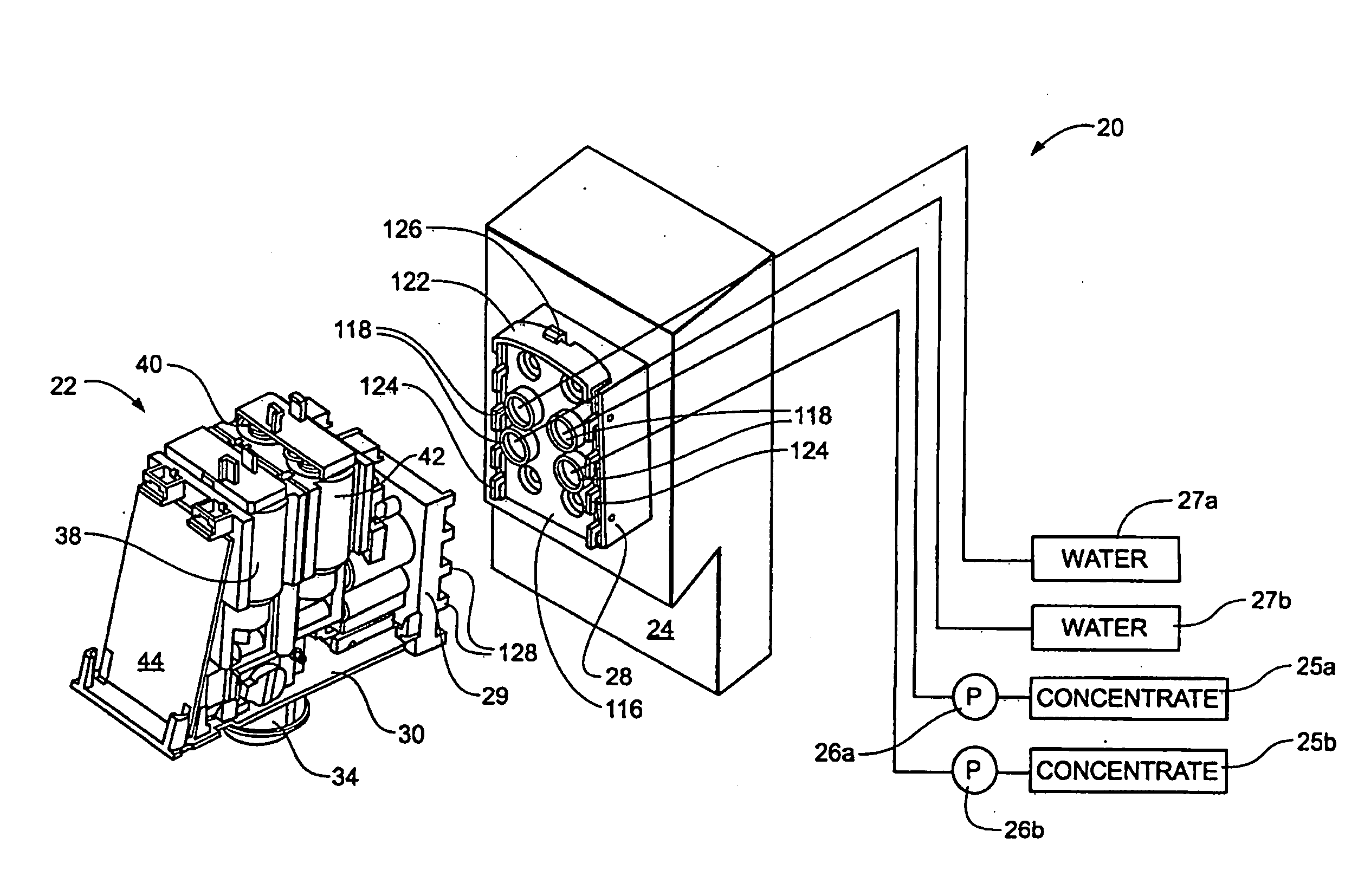
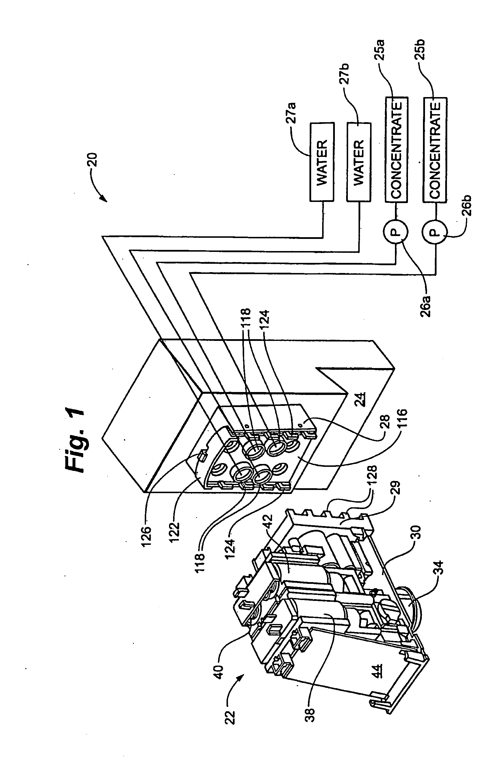
[0036]FIG. 1 illustrates a dispensing system 20, including a dispensing head 22, according to this invention, and a counter-located base 24, to which the dispensing head 22 is removably mounted. Different flavored concentrates, sometimes called syrups, are stored in containers or reservoirs 25a and 25b that are typically concealed from the user who is dispensing the beverages. Pumps 26a and 26b are connected to each concentrate container 25a and 25b, respectively. Each pump 26a and 26b pumps the associated concentrate through the base 24 and into the dispensing head 22. Two sources of water, represented by blocks 27a and 27b, are also connected to base 24. One source supplies a noncarbonated water stream. The second source includes a carbonator (not illustrated) that supplies carbon dioxide to the water stream it supplies through base 24 into the dispensing head 22.

[0037]The tubing (shown schematically, but not otherwise identified) through which these four fluid streams flow into t...


PUM

PropertyMeasurementUnit
lengthaaaaaaaaaa
volumeaaaaaaaaaa
forceaaaaaaaaaa

Abstract

A beverage dispensing system includes a base to which a dispensing head is removably attached without additional fasteners. Beverage-forming liquids are supplied through a plurality of separate conduits in the base. Each base conduit has a normally closed valve that normally blocks fluid flow. The dispensing head has at least one passageway that receives liquid from an associated one of the base conduits. A projection associated with each dispensing head passageway opens the associated conduit valve to allow fluid flow from the base to the head. Dispensing valves in the dispensing head regulate the dispensing of the beverage. By selectively opening the dispensing valves, a plurality of beverages are formed from combinations of one or more liquids. A dispensing head includes an inlet opening and an outlet opening at each end of a passage extending through a body, the inlet opening having a smaller cross-sectional area than the outlet opening.

Description

REFERENCE TO EARLIER FILED APPLICATION[0001]This application claims the benefit of U.S. Non-Provisional patent application Ser. No. 11 / 118,535, filed Apr. 29, 2005, which claims priority to U.S. Provisional Application No. 60 / 572,976, filed May 21, 2004. Each of these patent applications is entirely incorporated herein by reference.BACKGROUND OF THE INVENTION[0002]1. Field of the Invention[0003]The present invention relates generally to beverage dispensing systems for dispensing beverages such as carbonated beverages. More particularly, the present invention relates to a beverage dispensing system with a dispenser head capable of dispensing plural beverages.[0004]2. Description of the Related Art[0005]Often, at restaurants or other locations, a beverage is formed from a mixture of a concentrate and water. Depending on the particular beverage being formed, the water may or may not be carbonated. An advantage of dispensing beverages in this form is that the concentrate containers and ...

Claims


Application Information

Patent Timeline
Patent Type & Authority Applications(United States)
IPC IPC(8): B67D5/56B67D1/00B67D7/74B67D1/12
CPCB67D1/0021B67D1/0044B67D7/74B67D1/1272B67D7/06B67D1/0081Y10T137/0385B01F35/71805B01F23/40B01F25/105
Inventor BETHUY, TIMOTHY W.BLACK, WILLIAM J.CAHILL, BRIAN T.SCHILLING, RONALDNOVOTNY, PAULNEBBIA, FABIOPERUCCA, GIOVANNI
Owner PEPSICO INC
Why Eureka
Try Eureka