Reflector support structure

Active Publication Date: 2009-03-05
HONDA MOTOR CO LTD
View PDF23 Cites 5 Cited by
  • Summary
  • Abstract
  • Description
  • Claims
  • Application Information

AI Technical Summary

Benefits of technology

[0007]The present invention has been made to solve the foregoing problem and it is an object of an embodiment of the present invention to pr

Problems solved by technology

It is likely that a reflector mounted on a carrier wil

Method used


Image

  • Reflector support structure
  • Reflector support structure
  • Reflector support structure

Examples


Example

[0025]A specific embodiment to which the present invention is applied will be described below with reference to the accompanying drawings. Throughout the descriptions given hereunder, longitudinal, lateral, and vertical directions are relative to the vehicle body. In the drawings, an arrow FR denotes a vehicle forward direction, an arrow R denotes a vehicle rightward direction, and an arrow UP denotes a vehicle upward direction, respectively.

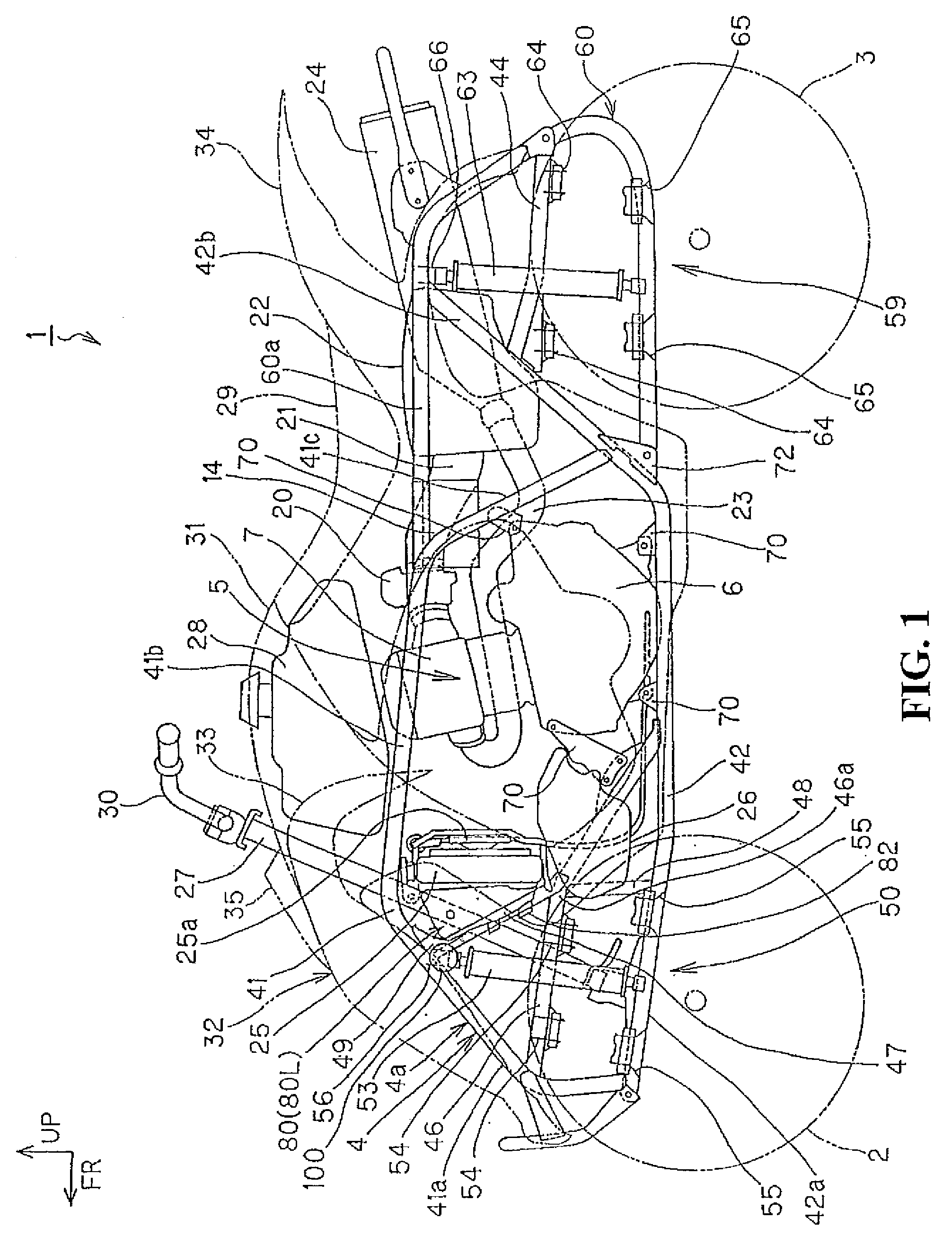
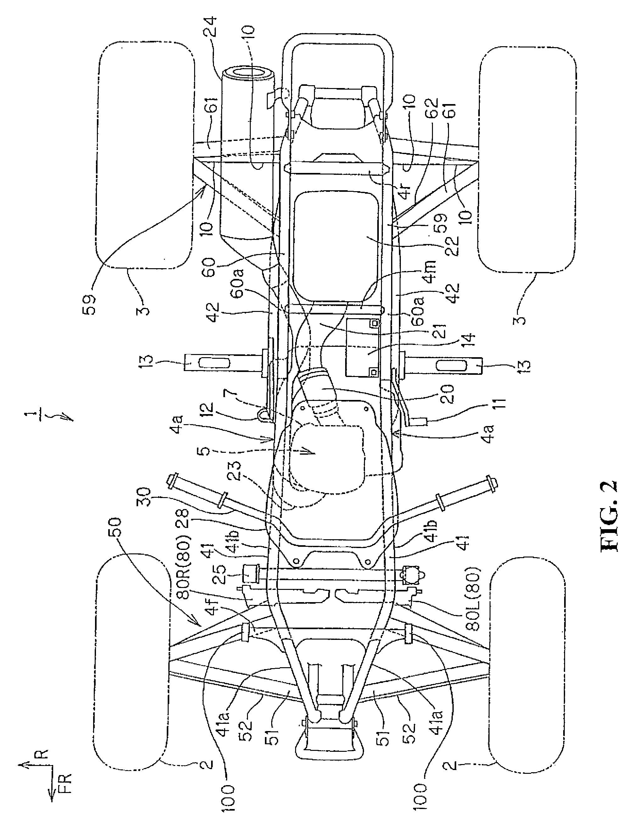
[0026]FIG. 1 is a side elevational view showing a saddle-riding type vehicle according to an embodiment of the present invention. FIG. 2 is a plan view showing the saddle-riding type vehicle according to an embodiment of the present invention.

[0027]A saddle-riding type vehicle 1 is a four-wheel vehicle categorized into the ATV (all terrain vehicle). The saddle-riding type vehicle 1 includes left and right front wheels 2 and rear wheels 3, each having a relatively large diameter, disposed at the front and rear of a compact and lightweight vehicle...


PUM


Abstract

A reflector support structure capable of reducing the effect on the appearance of a vehicle body, while maintaining good visibility. In a vehicle including a wheel disposed on a vehicle body frame via a suspension, a fender covering an upward area of the wheel, a cross frame disposed on an inside of the fender and extending laterally across the vehicle body frame, and a shock absorber having an upper end attached to the cross frame, a reflector is disposed visibly from an outside of the vehicle body on the cross frame disposed on the inside of the fender.

Description

CROSS-REFERENCE TO RELATED APPLICATIONS[0001]The present application claims priority under 35 USC 119 to Japanese Patent Application No. 2007-226442 filed on Aug. 31, 2007 the entire contents of which are hereby incorporated by reference.BACKGROUND OF THE INVENTION[0002]1. Field of the Invention[0003]The present invention relates to a reflector support structure for mounting a reflector so as to be visible from the outside of a vehicle body.[0004]2. Description of Background Art[0005]Saddle-riding type vehicles including ATVs (all terrain vehicles) (hereinafter referred to as “vehicle”) are known. See, for example, Japanese Patent Laid-Open No. 2006-096132. Such a vehicle is attached with a reflector for the improved visibility from the outside. Typically, the reflector is mounted on a rear carrier and designed to reflect light when illuminated from the rear of the vehicle. Some countries require that the reflector is mounted on a side surface of the vehicle.[0006]Because the mounti...

Claims


Application Information

Patent Timeline
IPC IPC(8): A47B96/06B62K5/00B62K5/01
CPCB60Q1/32B62K5/01B62J6/20
Inventor HIRUKAWA, MASAYUKI
Owner HONDA MOTOR CO LTD
Why Eureka
Try Eureka