[0004]It is evident that when a
lithium ion battery is charged with a large charging current at low temperature, lithium ions having moved from a positive electrode to a negative electrode via organic electrolytic solution are reluctant to be absorbed in the negative electrode, resulting in occurrence of deposition of a
lithium metal on the surface of the negative electrode. The lithium
metal deposited on the surface of the negative electrode does not return to the electrolytic solution as lithium ions. Therefore, when a flow of a large charging current is taken place at a low temperature, the deposited lithium
metal will be accumulated on the negative electrode, thereby increasing a possibility that the positive electrode and the negative electrode are short-circuited. Therefore, when charging is performed at a low temperature, it is necessary to maintain the charging current at a level equal to or smaller than the maximum charging current value Imax2, in order to prevent lithium
metal deposition on the negative electrode.
[0012]A non-limiting object of some embodiments is to provide a battery pack having accommodated therein a charging circuit capable of changing the value of a charging current based on the temperature associated with a
battery cell. Another object of some embodiments is to provide a battery pack capable of increasing an
internal temperature when performing charging in a low temperature range to reach a standard temperature range in a short time. A further object of some embodiments is to provide a battery pack having accommodated therein a charging circuit capable of performing charging with a plurality of charging current values without adding any modifications to an apparatus on which the battery pack is mounted. A still further object of some embodiments is to provide a method of charging a secondary battery accommodated in a battery pack based on a temperature associated with a
battery cell.
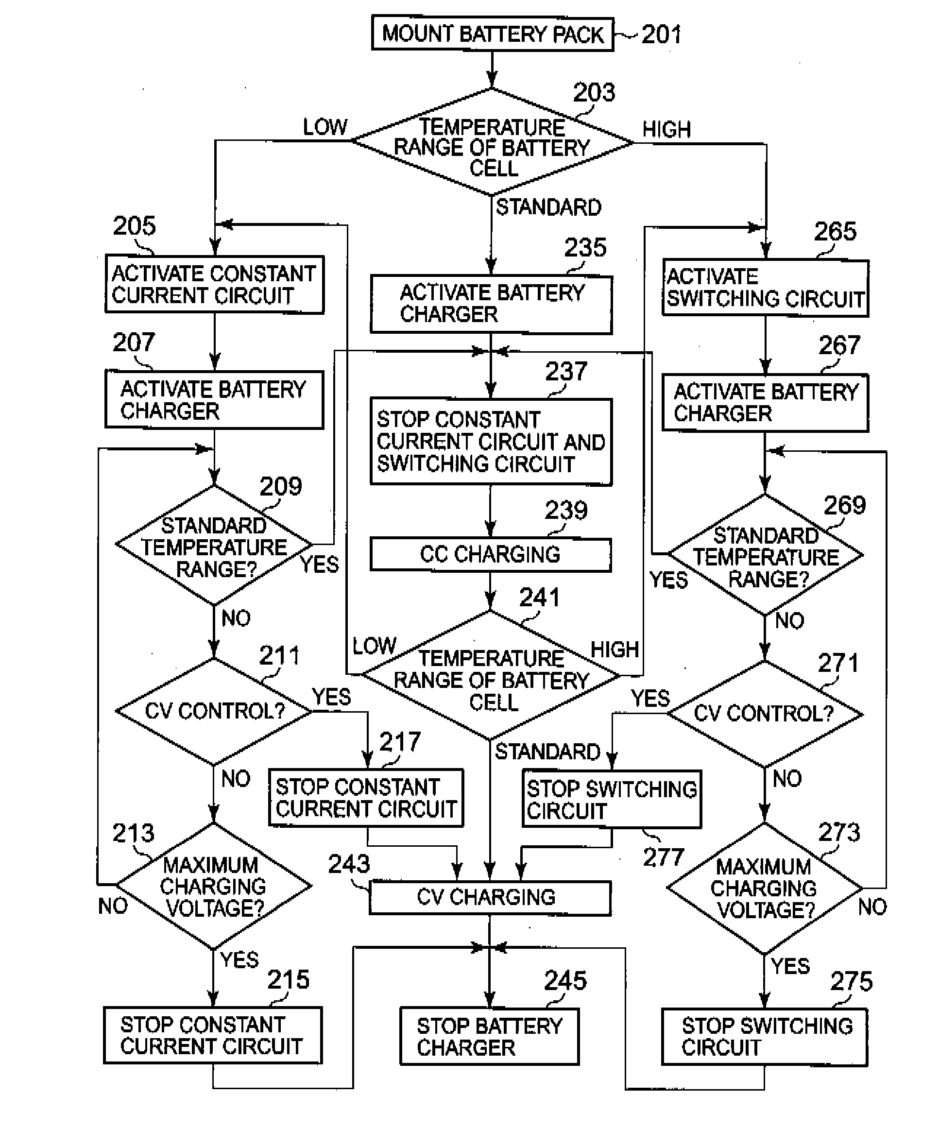
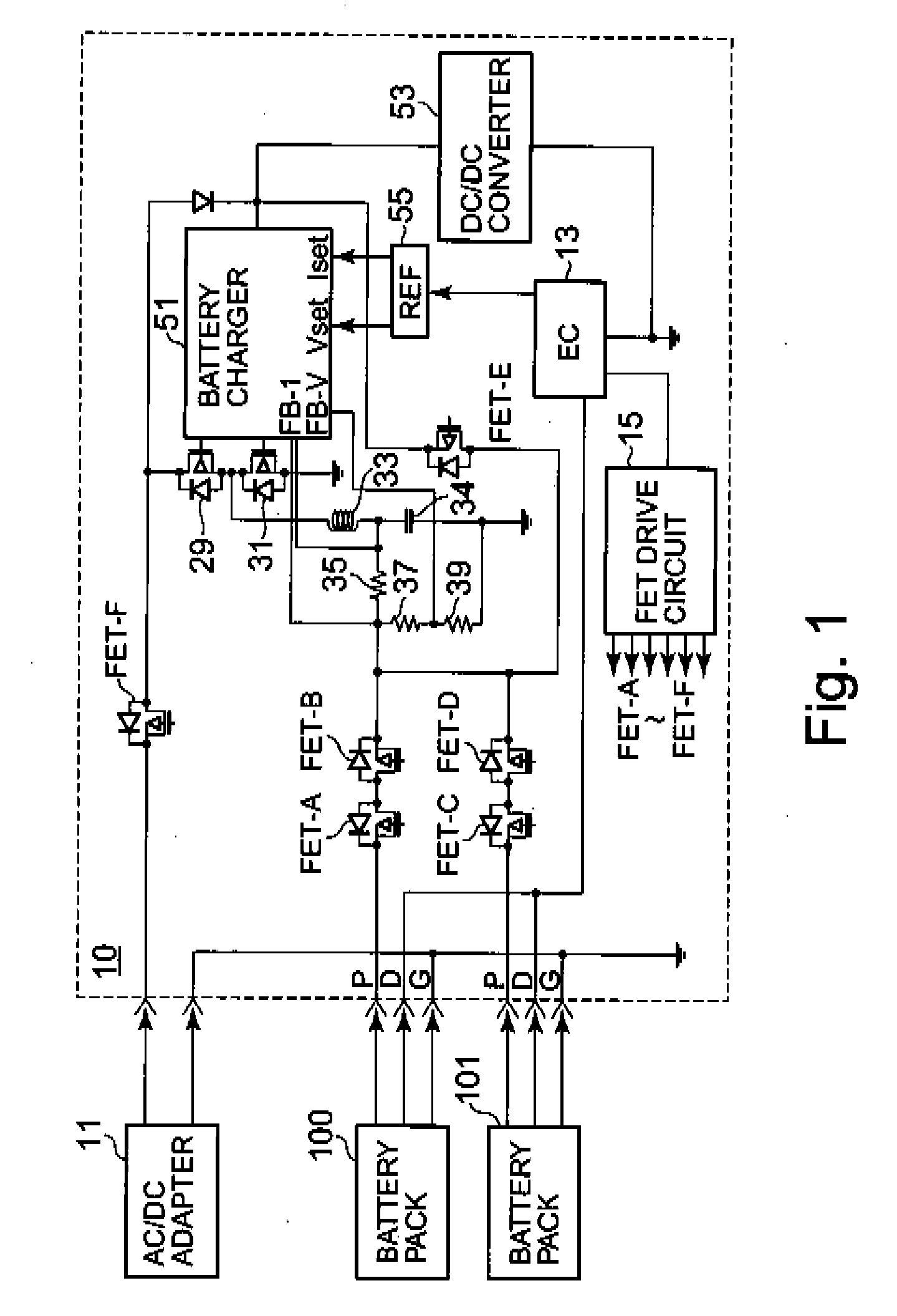
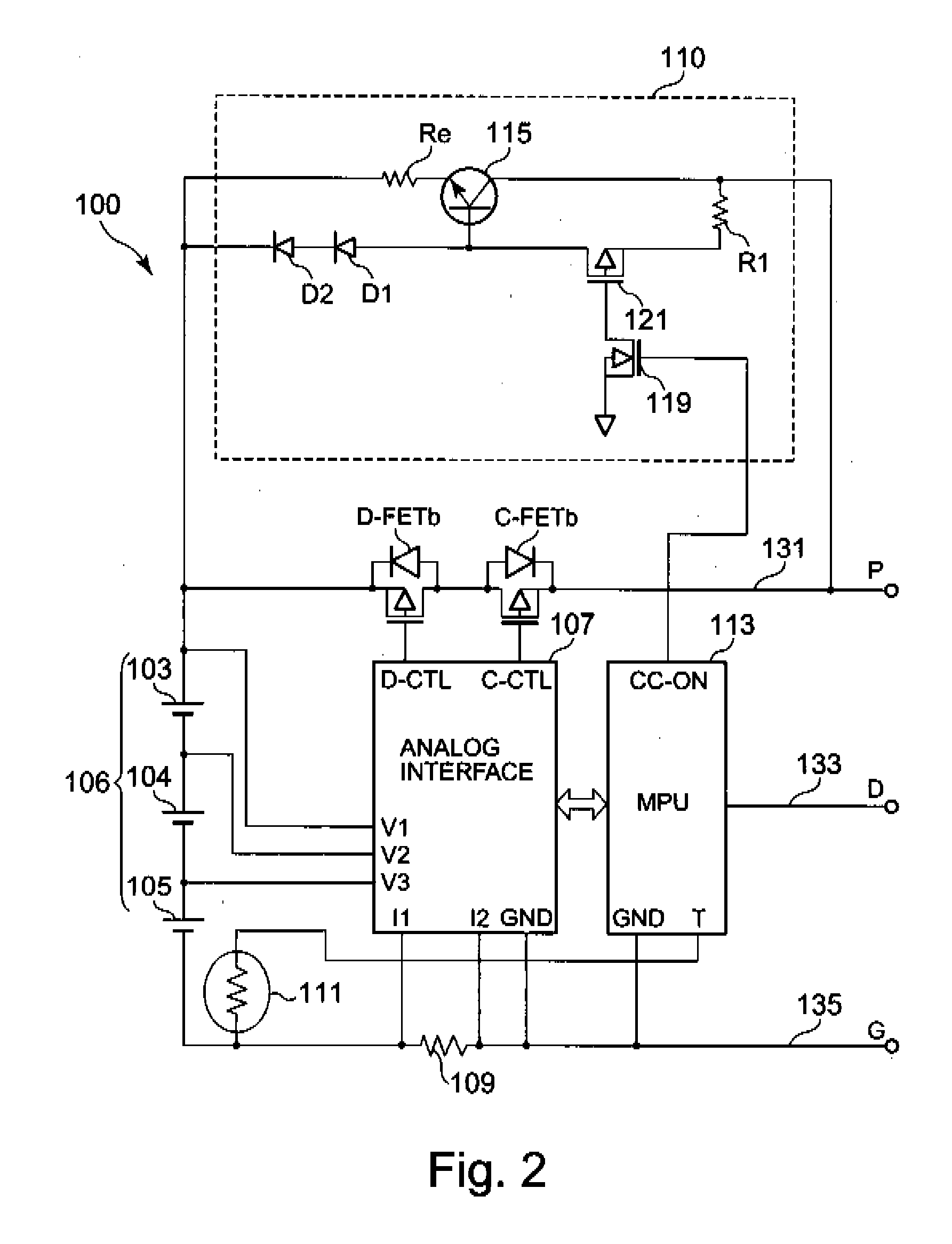
[0014]Even when the DC power supply is a battery charger that operates with a single setting current, the first charging circuit on the battery pack side can generate a charging current as needed depending on the temperature of the battery
cell and perform charging. When the first charging circuit generates the charging current by continuously controlling
semiconductor elements, heat may generate from the
semiconductor elements; however, in some embodiments, the
heat generation is used to ensure safety. Specifically, by operating the first charging circuit only when the temperature of the battery
cell belongs to the low temperature range, it is possible to increase the temperature of the battery
cell in a short period of time to thusly prevent lithium metal from depositing. Moreover, after the temperature of the battery cell is increased to the standard temperature range in a short period of time, the charging can be performed with the maximum charging current allowed in the standard temperature range; therefore, it is possible to decrease the charging time.
[0015]The battery pack may further include a second charging circuit. The second charging circuit can generate a switching current lower than the charging current from the charging current per se. In this case, the
control unit may control the operation of the battery pack in a manner such that the secondary battery is charged by the second charging circuit when it is determined that the temperature in connection with the secondary battery belongs to a high temperature range higher than the standard temperature range. The value of the switching current can be represented by the average values and the difference between the average value and the
peak value may be relatively large. However, since in the high temperature range, it is only necessary to prevent any temperature rise in the battery, the charging can be performed with the switching current generated with a duty ratio that satisfies the average value determined based on the temperature rise. Moreover, since the cycle of the switching operation can be extended to a range necessary for preventing the temperature rise, there is no problem of
heat generation or electromagnetic disturbance due to the switching operation.
[0018]When the temperature of the battery cell belongs to the standard temperature range during charging by the first or second charging circuit, the charging can be performed by the battery charger, whereby the charging current is not limited to more than that needed, and the charging time is not increased. When the temperature of the battery cell belongs to the high temperature range while the charging is performed by means of the battery charger, the charging can be continued by the second charging circuit without necessity of stopping the charging. When the
voltage of the secondary battery has reached the maximum charging
voltage that is allowed in the low temperature range or the high temperature range while charging is still being performed by the first charging circuit or the second charging circuit, the charging can be stopped and therefore, the safety can be ensured.
[0019]In accordance with the above-mentioned various aspects of present principles, it is possible to provide a battery pack having accommodated therein a charging circuit capable of changing the current value of a charging current based on the temperature in connection with a battery cell. Further, it is possible to provide a battery pack capable of increasing an
internal temperature when performing charging in a low temperature range to reach a standard temperature range in a short period of time. Furthermore, it is possible to provide a battery pack having accommodated therein a charging circuit capable of performing charging with a plurality of charging current values without adding any modifications to an apparatus on which the battery pack is mounted. Furthermore, it is possible to provide a method of charging a secondary battery accommodated in a battery pack based on the temperature associated with the secondary battery.


