Image sensor with high dynamic range in down-sampling mode

a high-dynamic range, image sensor technology, applied in the field of image sensors, can solve the problems of increasing the cost of the image sensor, and achieve the effects of high dynamic range, reduced vertical resolution, and reduced vertical resolution

Active Publication Date: 2009-03-05
OMNIVISION TECH INC
View PDF7 Cites 57 Cited by
  • Summary
  • Abstract
  • Description
  • Claims
  • Application Information

AI Technical Summary

Benefits of technology

[0007]An image sensor includes an array of photo-sensitive pixels arranged in a row and in column format with a line-by-line read out sequence of the rows. The image sensor has a full resolution mode and at least one down-sampling mode. In a down-sampling mode the vertical pixel resolution is reduced. For a down-sampling mode having at least a 1:2 reduction in vertical resolution, a high dynamic range is also achieved by varying the exposure time of the rows according to an alternating sequence of row exposure times. Data from sets of rows that are combined to achieve down-sampling also have different row exposure times. As a result, a high dynamic range is achieved for the down-sampling mode.

Problems solved by technology

In particular, conventional approaches to achieve a high dynamic range typically require significant increases in chip area and / or a more complex fabrication process, which increases the cost of the image sensor.

Method used


Image

  • Image sensor with high dynamic range in down-sampling mode
  • Image sensor with high dynamic range in down-sampling mode
  • Image sensor with high dynamic range in down-sampling mode

Examples


Embodiment Construction

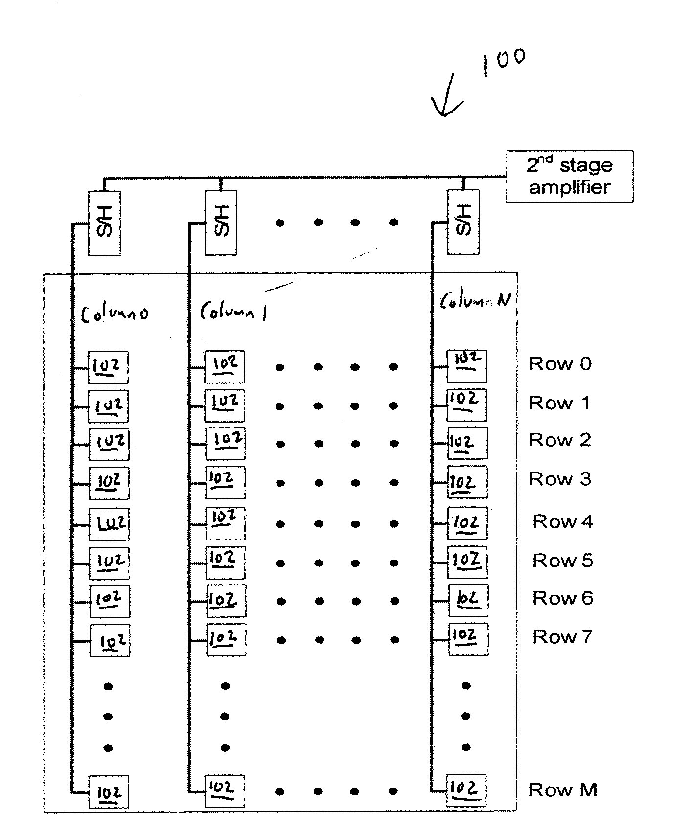
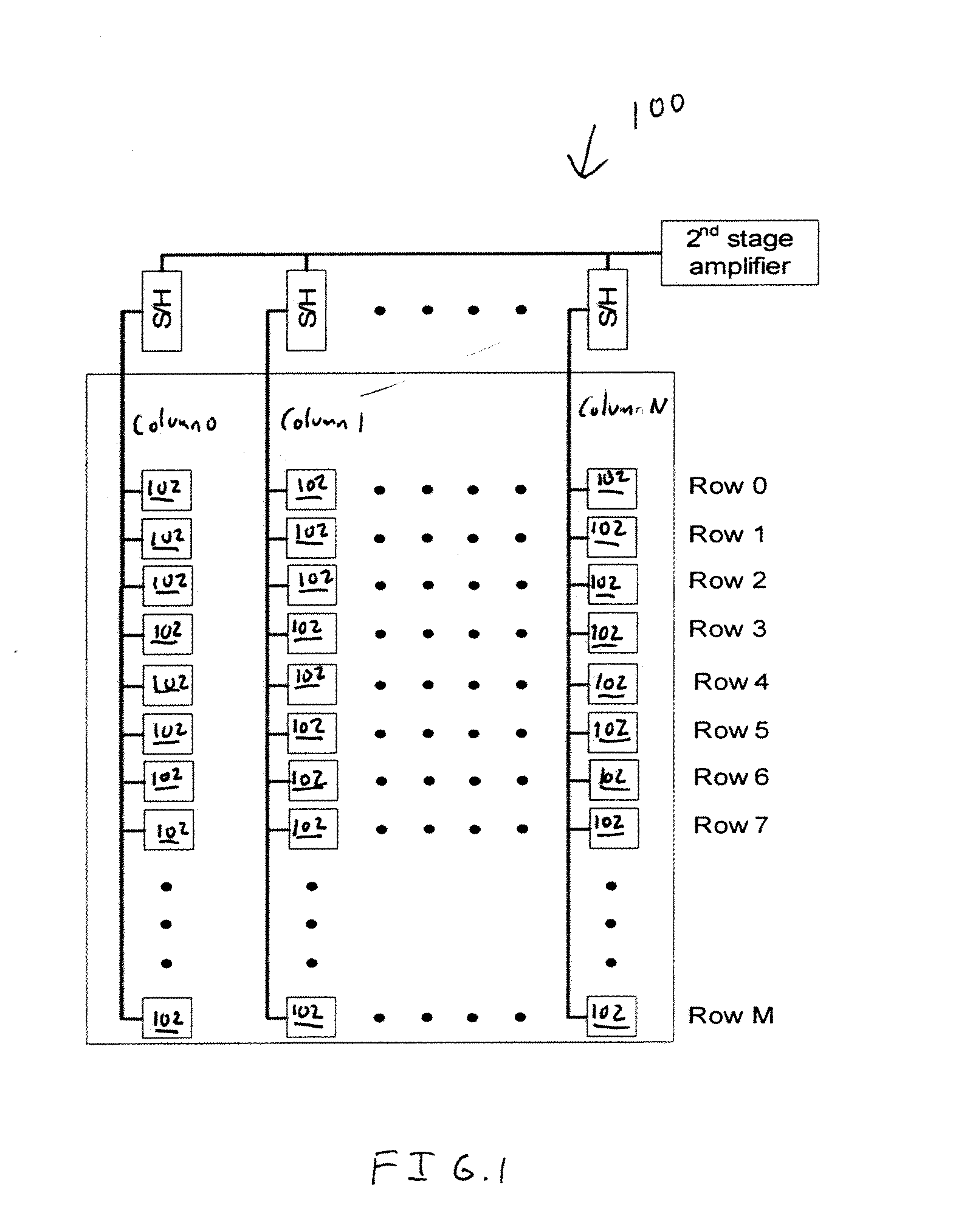
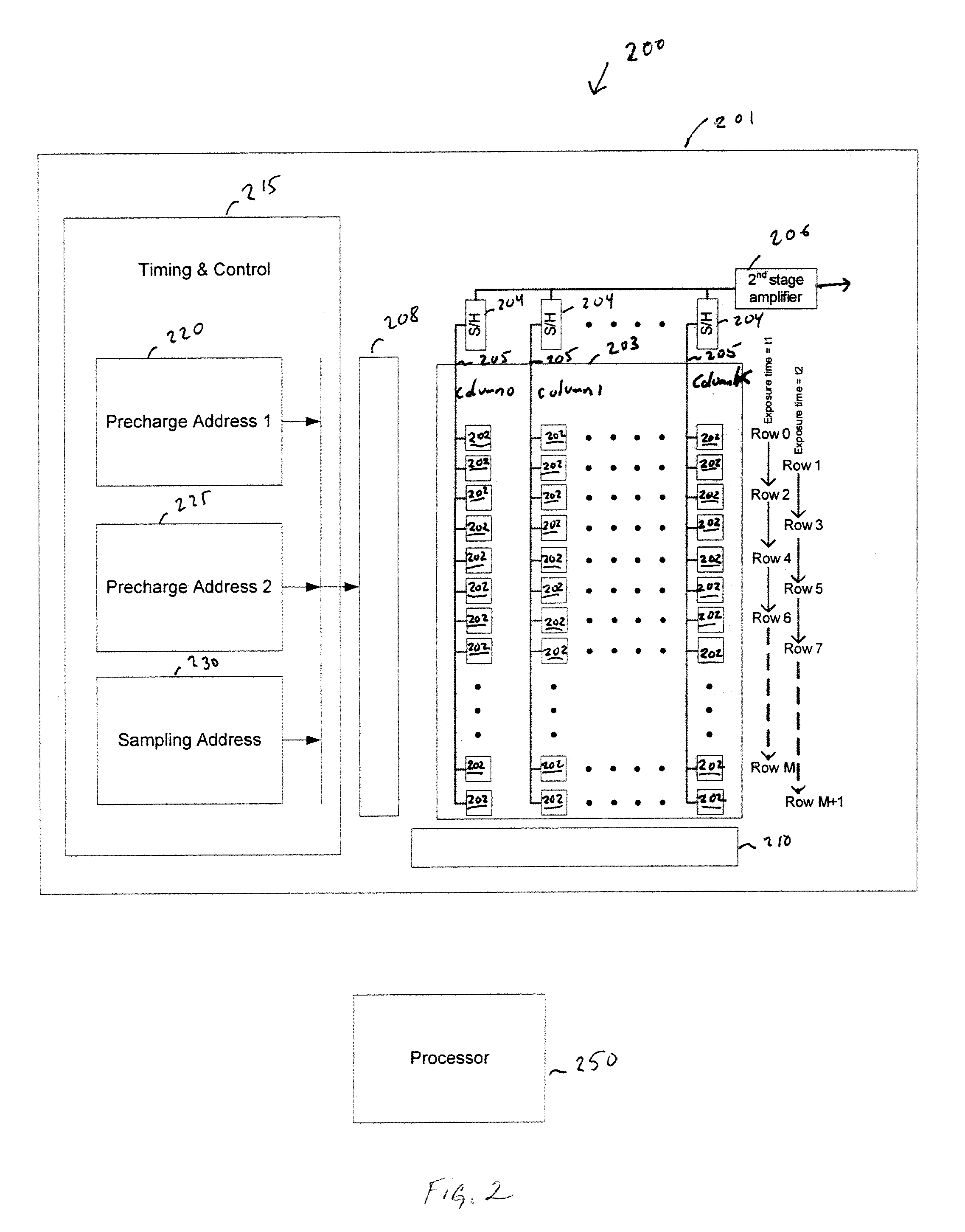
[0014]FIG. 2 is a block diagram of one embodiment of an image sensing system 200 of the present invention that supports a high dynamic range in a down-sampling mode. Some conventional well-known components are omitted for clarity. An image sensor 201 includes an array 203 of individual photo-sensitive pixels 202 arranged in rows and columns (for the purposes of clarity, some of the columns and pixels and individual pixels are omitted, as illustrated by the dots). The image sensor may, for example, be implemented as a CMOS image sensor with each pixel 202 including a photodetector and associated circuitry to support setting an exposure time and performing read out.

[0015]The array 203 is illustrated as having a column parallel read out architecture in which pixels 202 in a row are read out simultaneously and processed in parallel in a line-by-line sequence. That is, Row 0 is read out, then Row 1, then Row 2, and so on until Row M +I is read out. Sample and Hold (S&H) elements 204 conn...


PUM


Abstract

An image sensor has an array of photo-sensitive pixels and supports a line-by-line read out of rows. In a normal resolution each row has the same nominal gain and exposure time. In a down-sampling mode the exposure times of the rows are varied according to an alternating sequence having at least two different exposure times. During down-sampling, raw pixel data from rows with different exposure times is combined to simultaneously achieve down-sampling and a high dynamic range.

Description

FIELD OF THE INVENTION[0001]The present invention is generally related to image sensors. More particularly the present invention is related to image sensors having a high dynamic range.BACKGROUND OF THE INVENTION[0002]CMOS image sensors typically include an array of pixels. Each pixel includes a photodetector that transforms incident light photons into current signals. Additionally, a pixel in a CMOS image sensor also includes other well-known elements to set the exposure time of the photodetector and perform a read out, such as a reset switch, signal amplifier, and output circuits. An individual pixel has an output that for a fixed exposure time eventually saturates with increasing light intensity.[0003]FIG. 1 illustrates a CMOS image sensor 100. The pixel array 100 has pixels 102 arranged into a set of columns and rows having a column parallel read out architecture in which pixels in a row are read out simultaneously and processed in parallel. That is, Row 0 is read out, then Row ...

Claims


Application Information

Patent Timeline
Patent Type & Authority Applications(United States)
IPC IPC(8): H04N5/335H04N3/14
CPCH04N5/2353H04N5/2355H04N5/343H04N9/045H04N5/347H04N5/35554H04N5/3458H04N23/73H04N23/741H04N25/42H04N25/46H04N25/583H04N25/447H04N25/136H04N25/134
Inventor LUO, XIAODONGYANG, HONGLI
Owner OMNIVISION TECH INC
Why Eureka
Try Eureka