Zoom lens device

a zoom lens and lens body technology, applied in the direction of mountings, instruments, mountings, etc., can solve the problems of difficult formation of each groove, disadvantageous size reduction, and the diameter of the zoom cam b>3/b> to become larger, etc., to achieve simple structure, reduce the play of the cam mechanism, and improve the effect of accuracy

Inactive Publication Date: 2009-03-05
PANASONIC CORP
View PDF1 Cites 3 Cited by
  • Summary
  • Abstract
  • Description
  • Claims
  • Application Information

AI Technical Summary

Benefits of technology

[0045]Accordingly, according to the zoom lens device, in addition to the above action and effect, since the stopwork is formed of a parallel indexing drive, the play of the cam mechanism can be decreased despite of the simple structure, and it is advantageous for the zoom operation performed with higher accuracy.
[0046]As described above, according to the zoom lens device of the present invention, the zoom mechanism realizes so-called step zoom operation such that at least one lens group out of the lens groups is moved in a step-like fashion in the same direction as the optical axis in such manner as to repeat the state of stop and the state of move, and also, in each zoom step (in the state of stop) of such a step zoom, the focus mechanism moves at least one of the zoom mechanisms in the same direction as the optical axis, thereby making the focus adjustment. That is, as compared with the conventional example wherein the locus of lens movement or zooming is partially utilized for focusing, it is possible to make the focus operation more independent of the zoom operation. Accordingly, according to the zoom lens device, even in case of using an optical system wherein the locus of lens movement for focusing, for example, greatly deviates from that of zoom movement, it is possible to provide a step zoom device coping with every lens design because of being able to make the focus adjustment in each zoom step. Particularly, in the case of using a zoom optical system wherein the focus movement is made by moving a lens group closer to the object side, it is generally easy to maintain the accuracy because the amount of focus movement is very large and it is effective to improve the quality of the zoom lens device.

Problems solved by technology

However, such a multi-focus magnification switching lens-barrel is formed with a power varying cam groove, focusing cam groove, and guide groove in a rotary barrel, and therefore, in case of mounting it in a very small camera built into a portable electronic apparatus such as a portable telephone, it is difficult to form each groove because the rotary barrel is too small.
In the zoom lens device described above, if the number of steps is increased to cope with various zooms, the number of flat portions of zoom cam surface 8 increases causing the zoom cam 3 to become larger in diameter, and this is disadvantageous to the size reduction.
Contrarily, if the number of steps is decreased, it is possible to reduce the size, but the number of zoom patterns is limited, and the value as a zoom lens device is lowered.
However, the locus of focus movement greatly deviates from the locus that follows the zoom movement.
In other words, in the case of a zoom optical system based on optical design such that the locus of focus movement and the locus of zoom movement are highly independent of each other, it is difficult to realize practically appropriate step zoom operation by using the configuration of the conventional example.
Accordingly, in the case of the latter zoom optical system, it is difficult to configure a step zoom lens device by using the configuration of the conventional example.
There still exists a problem as mentioned above, it is unable to provide a high-quality zoom lens device by using such a zoom optical system.

Method used


Image

  • Zoom lens device
  • Zoom lens device
  • Zoom lens device

Examples


embodiment 1

Preferred Embodiment 1

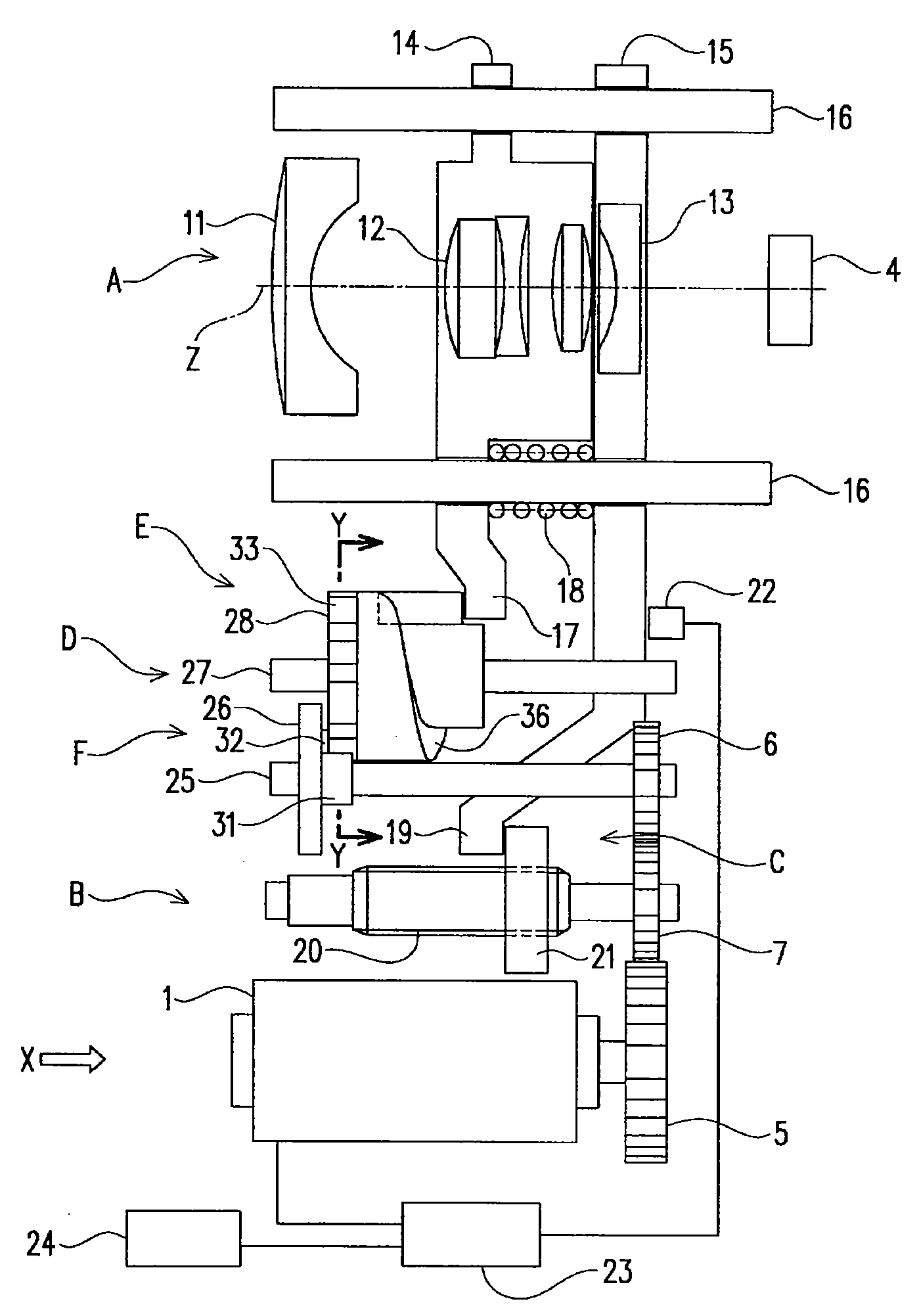
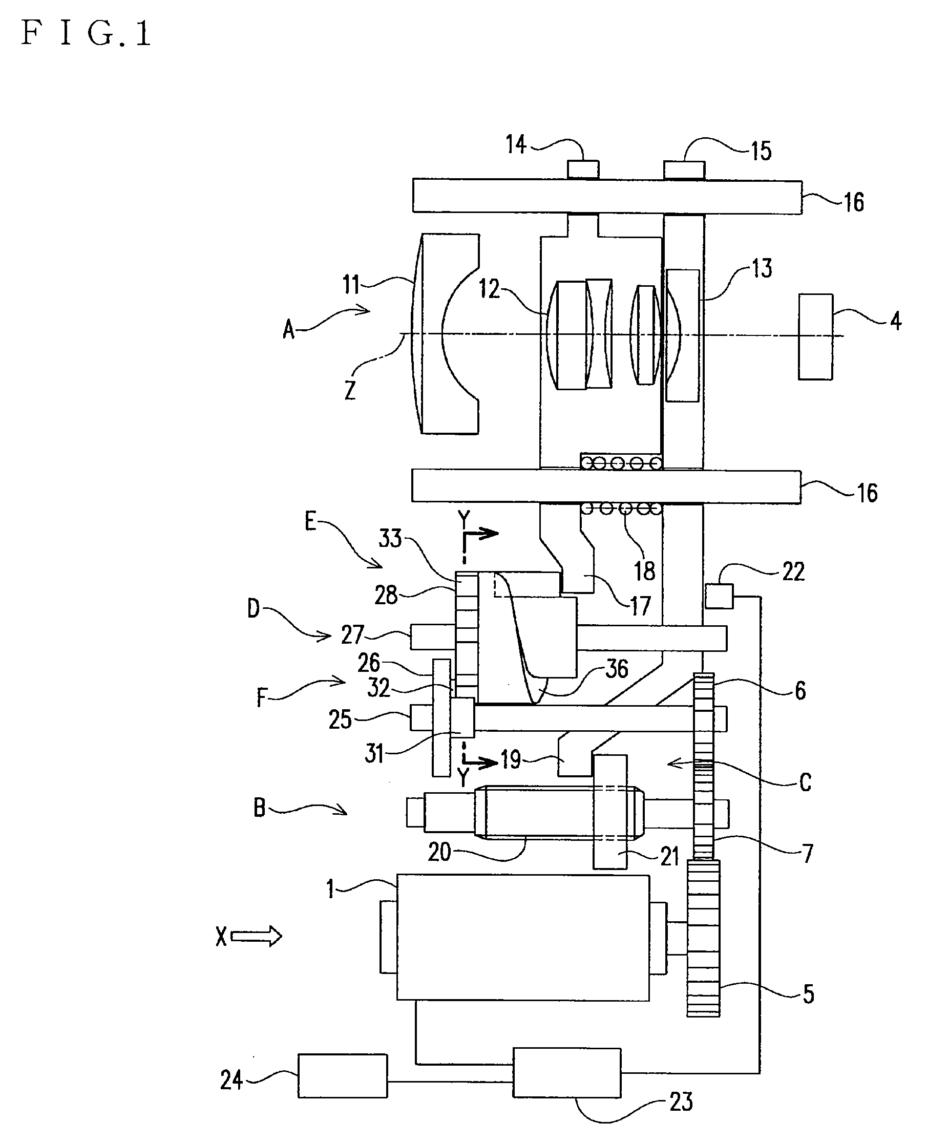
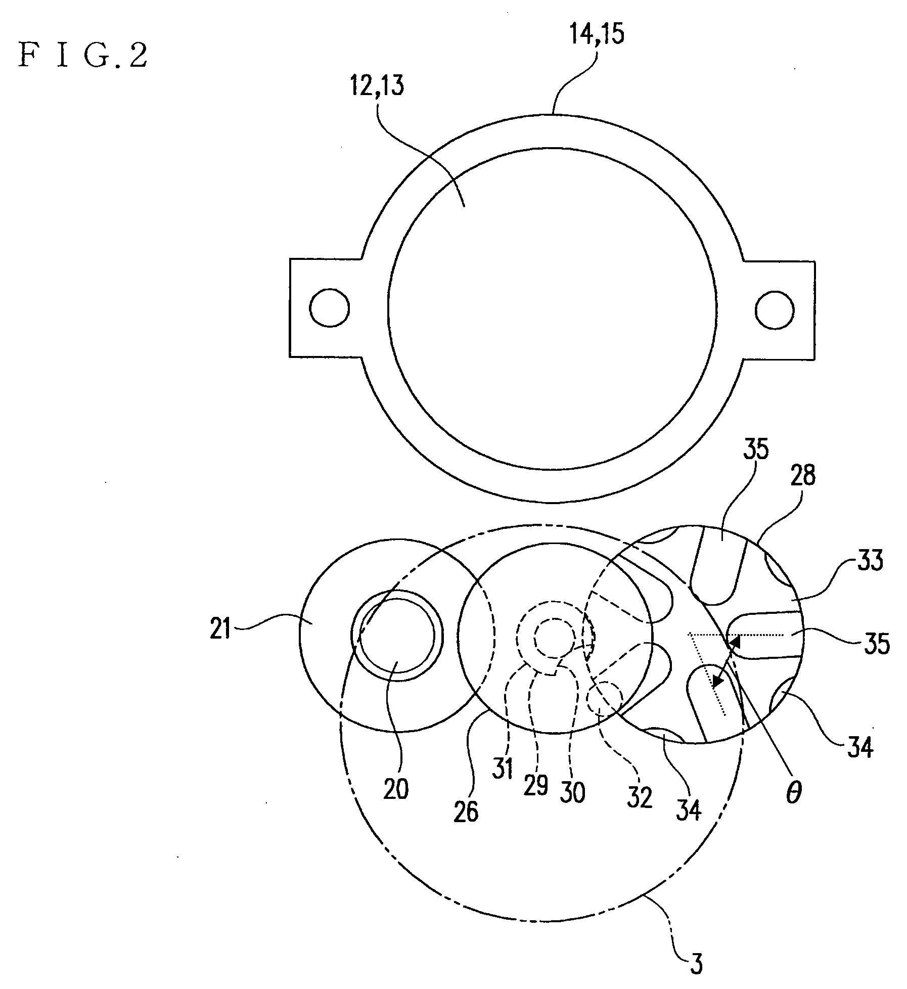
[0099]The first preferred embodiment of the present invention will be described with reference to FIG. 1 to FIG. 4. The same components as the conventional ones and the equivalents are given same reference numerals, and the description is omitted. This zoom lens device comprises lens system A, driving force transmitting section B, focus mechanism C, stopwork D, and zoom mechanism E.

[0100]Lens system A comprises, as shown in FIG. 1, first lens group 11, second lens group 12, and third lens group 13 which are arranged in order on optical axis Z from the outer side (at the left in FIG. 1) to the inner side (at the right side in FIG. 1), where third lens group 13 confronts pickup element 4. First lens group 11 is held by a holding frame (not shown) which is immovable. Second lens group 12 and third lens group 13 are respectively held by second holding frame 14 and third holding frame 15 which are individually movable. Paired guide shafts 16 pierce the second holdin...

embodiment 2

Preferred Embodiment 2

[0122]The zoom lens device in the second preferred embodiment of the present invention will be described in the following with reference to FIG. 5 and FIG. 6. The same components as in the conventional example and the first preferred embodiment and the equivalents are given same reference numerals in the description.

[0123]The zoom lens device in the second preferred embodiment is characterized in that third lens group 13 moves non-linearly. Therefore, the zoom lens device is such that focus mechanism C is provided with gear array 37 and spiral focus cam surface 38.

[0124]Gear array 37 serves to reduce the rotating speed of second gear 7, and it comprises pinion 39 coaxial with second gear 7, large gear 40 engaging the pinion 39, pinion 41 coaxial with large gear 40, and large gear 42 engaging the pinion 41. And, rotary shaft 43 same in direction as optical axis Z is fixed on large gear 42, and rotary shaft 43 is provided with focus cam surface 38.

[0125]Focus cam...

embodiment 3

Preferred Embodiment 3

[0129]The zoom lens device in the third preferred embodiment of the present invention will be described in the following with reference to FIG. 7. The third preferred embodiment is characterized in that stopwork D is parallel indexing drive G as shown in FIG. 7. The other configuration is same as for the zoom lens device in the first or second preferred embodiment.

[0130]Parallel indexing drive G is configured in that driving wheel 44 and driven wheel 45 are combined with each other, and driving wheel 44 is formed with extension 47 on plate cam 46. Driven wheel 45 is provided with a plurality of pins 48 (four pins in the figure, but the number of pins is not limited) engaging plate cam 46 which are concentrically projected from disk 49. Extension 47 serves to give a rotational force to pin 48, thereby rotating the driven wheel 45. Driving wheel 44 is fixed on driving shaft 25, and driven wheel 45 is fixed on driven shaft 27.

[0131]Since the third preferred embodi...


PUM


Abstract

A zoom lens device is reduced in size and capable of zoom operation with the number of steps large enough to display the value as a zoom lens. The zoom lens device comprises lens system (A) with a first lens group, a second lens group, and a third lens group arranged on optical axis (Z). It comprises zoom mechanism (E) for changing the focal distance of lens system (A) by changing the second lens group in the direction of optical axis (Z). It comprises focus mechanism (C) for adjusting the image forming position of lens system (A) by moving the third lens group13 in the same direction as optical axis (Z). It also comprises driving force transmitting section (B) for transmitting the driving force from the motor to zoom mechanism (E) and focus mechanism (C). Driving force transmitting section (B) includes stopwork (D) like Geneva drive (F) for intermittently transfer the driving force from the driving source to zoom mechanism (E).

Description

TECHNICAL FIELD[0001]The present invention relates to a zoom lens device having a plurality of lens groups mounted in a camera or the like, and more particularly, it relates to a zoom lens device comprising a zoom mechanism of which the lens group position changes in a step-like fashion.BACKGROUND ART[0002]A multi-focus magnification switching lens-barrel which is mounted in a camera in such manner as to move a plurality of lens groups between the position of a short focal distance and the position of a long focal distance, and is provided with a step zoom mechanism for selecting a plurality of focal distances is disclosed in Japanese Laid-Open Patent H9-329733. The multi-focus magnification switching lens-barrel has a fixed barrel inserted in a rotary barrel, and in the fixed barrel are inserted the first moving barrel holding the front group lenses and the second moving barrel holding the rear group lenses.[0003]The rotary barrel is formed with a power varying cam groove for front...

Claims


Application Information

Patent Timeline
Patent Type & Authority Applications(United States)
IPC IPC(8): G02B7/04
CPCF16H27/06G02B15/14G02B7/102G02B15/143
Inventor YAGI, FUMIYA
Owner PANASONIC CORP
Why Eureka
Try Eureka