Heat dissipation assembly

a technology of heat dissipation assembly and ductwork, which is applied in the direction of cooling/ventilation/heating modification, semiconductor/solid-state device details, semiconductor devices, etc., can solve the problems of inconvenient manipulating tools and the inability to provide fins at the shoulders

Inactive Publication Date: 2009-03-05
FU ZHUN PRECISION IND SHENZHEN +1
View PDF7 Cites 3 Cited by
  • Summary
  • Abstract
  • Description
  • Claims
  • Application Information

AI Technical Summary

Benefits of technology

[0008]A heat dissipation assembly is disclosed for dissipating heat generated by an electronic component. The heat dissipation assembly includes a heat sink assembly contacting the electronic component, a pair of retaining members fixed on two lateral sides of a top portion of the heat sink assembly, a pair of arms pivotably secured to the retaining members respectively, and an operating member pivotably attached to the retaining members. The operating member has two cams interacting with the arm and the heat sink assembly, respectively. When the operating member is rotated from a vertical orientation to a horizontal orientation, the arms are driven by the operating member to rotate towards the heat sink assembly and engage with barbs of a retention module. Furthermore, the heat sink is depressed and the arms are moved upwardly by the operating member to have a secure engagement with the barbs, whereby the heat sink assembly has an intimate contact with the electronic component.

Problems solved by technology

However, in this patent, the fins cannot be provided at the pair of shoulders due to the spaces being occupied by the clips.
Moreover, it is inconvenient in manipulating the tool to assemble the clips and the heat sink to the retention module.

Method used


Image

  • Heat dissipation assembly
  • Heat dissipation assembly
  • Heat dissipation assembly

Examples


Embodiment Construction

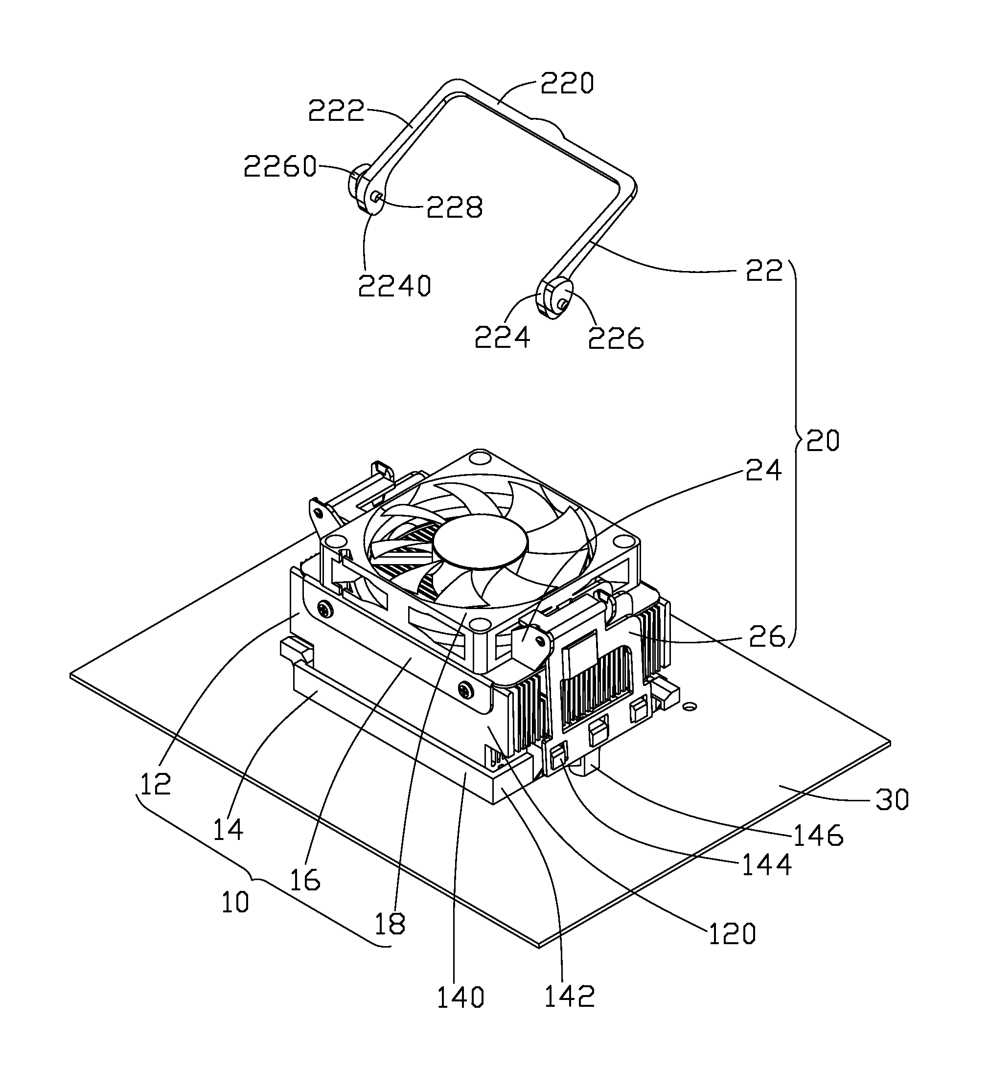
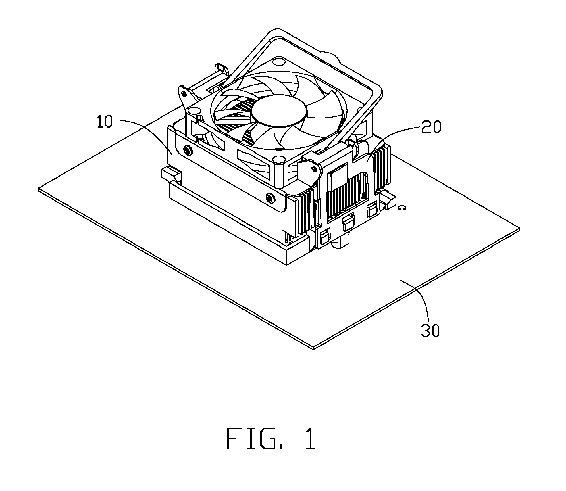
[0020]Referring to FIG. 1, a heat dissipation assembly in accordance with a preferred embodiment of the present invention comprises a heat sink assembly 10 for dissipating heat generated by an electronic component (not shown) mounted on a printed circuit board 30, and a locking device 20 for securing the heat sink assembly 10 on the electronic component.

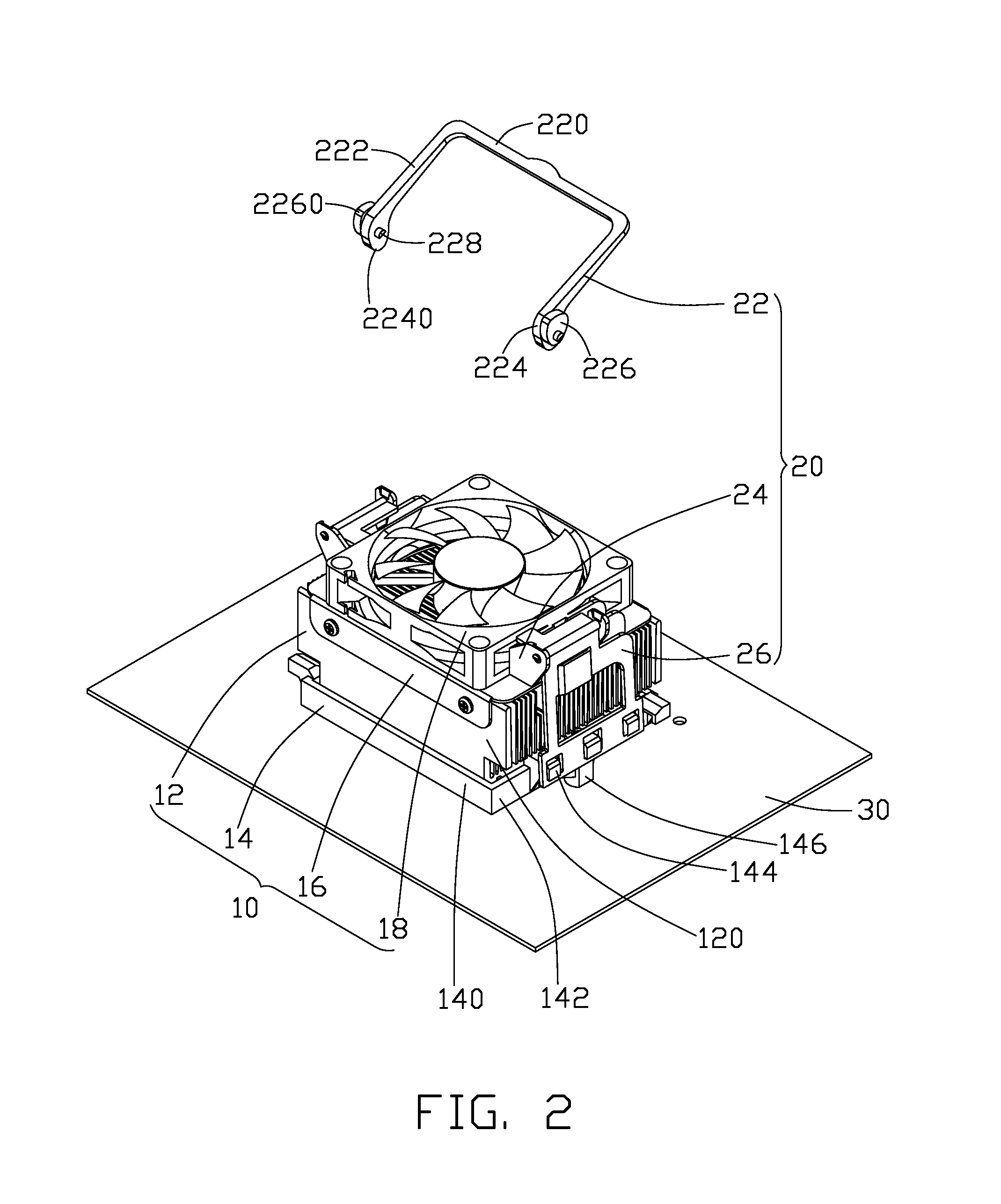
[0021]As shown in FIG. 2, the heat sink assembly 10 comprises a heat sink 12, a retention module 14 enclosing the heat sink 12, a cover 16 covering the heat sink 12, and a fan 18 mounted on the cover 16. The heat sink 12 comprises a base (not shown) having a bottom face contacting the electronic component, and a plurality of fins 120 extending upwardly and perpendicularly from a top face of the base. The retention module 14 has a rectangular configuration, and comprises a pair of opposite walls 140 and another pair of opposite walls 142 interconnecting the pair of opposite walls 140, wherein the pair of opposite walls 140 and said an...


PUM


Abstract

A heat dissipation assembly for dissipating heat generated by an electronic component includes a heat sink contacting the electronic component, a pair of retaining members fixed on two lateral sides of a top portion of the heat sink, a pair of arms pivotably secured to the retaining members, and an operating member pivotably attached to the retaining members. The operating member has two cams for interacting with the retaining member and the heat sink. When the operating member is rotated from a vertical orientation to a horizontal orientation, the arms are driven by the operating member to rotate towards the heat sink to engage with barbs of a retention module. Furthermore, the arms are also activated to move upwardly so they can tightly engage with the barbs, thereby securing the heat sink to the electronic component.

Description

BACKGROUND OF THE INVENTION[0001]1. Field of the Invention[0002]The present invention relates to a heat dissipation assembly, and more particularly to a heat dissipation assembly incorporating a locking device for securing a heat sink to a printed circuit board conveniently.[0003]2. Description of Related Art[0004]As computer technology continues to advance, electronic components such as central processing units (CPUs) of computers are made to provide faster operational speed and greater functional capabilities. When a CPU operates at a high speed in a computer enclosure, its temperature increases greatly and dramatically. It is desirable to dissipate the generated heat quickly, for example, by using a heat sink attached to the CPU in the enclosure. This allows the CPU and other electronic components in the enclosure to function within their normal operating temperature ranges, thereby assuring the quality of data management, storage and transfer. Generally, a locking device is requ...

Claims


Application Information

Patent Timeline
Patent Type & Authority Applications(United States)
IPC IPC(8): H05K7/20
CPCH01L23/4093H01L23/467H01L2924/0002H01L2924/00
Inventor LI, MINMA, WU-JIANG
Owner FU ZHUN PRECISION IND SHENZHEN
Why Eureka
Try Eureka