Cooling device coated with carbon nanotube and of manufacturing the same

a technology of carbon nanotube and cooling device, which is applied in the direction of coating, chemical apparatus and processes, electrical apparatus construction details, etc., can solve the problems of overheating, malfunction and breakage of components, elevated surface temperatures, etc., to achieve the effect of improving thermal exchange efficiency, maximizing thermal exchange efficiency, and reducing the size of electronic devices

Inactive Publication Date: 2009-03-05
KIM YONG HYUP +7
View PDF7 Cites 27 Cited by
  • Summary
  • Abstract
  • Description
  • Claims
  • Application Information

AI Technical Summary

Benefits of technology

[0016]The present invention can maximize thermal exchange efficiency by forming a carbon nanotube structure on a cooling device.
[0017]Also, the cooling device can become small-sized by improving the thermal exchange efficiency. Thus, electronic devices can be downscaled, and heat generated by a highly integrated electronic circuit chip can be effectively radiated. Consequently, an operating circuit can improve in lifetime and performance.

Problems solved by technology

When the electronic components operate under breaking load, their surface temperatures are elevated and they are overheated due to generated heat.
Thus, there is a strong possibility of causing malfunction and breakage of the components.

Method used


Image

  • Cooling device coated with carbon nanotube and of manufacturing the same
  • Cooling device coated with carbon nanotube and of manufacturing the same
  • Cooling device coated with carbon nanotube and of manufacturing the same

Examples


Embodiment Construction

[0022]The present invention will now be described more fully hereinafter with reference to the accompanying drawings, in which exemplary embodiments of the invention are shown. In the drawings, the forms and thicknesses of layers may be exaggerated for clarity, and the same reference numerals are used to denote the same elements throughout the drawings.

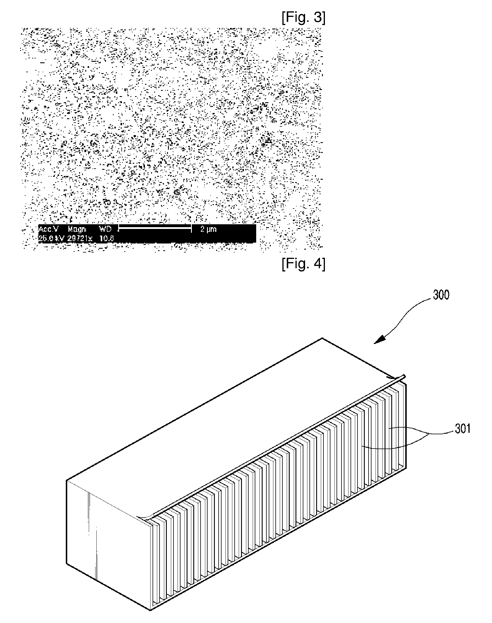
[0023]FIG. 3 is a photograph of a surface of a cooling fin to which carbon nanotubes are absorbed according to an exemplary embodiment of the present invention.

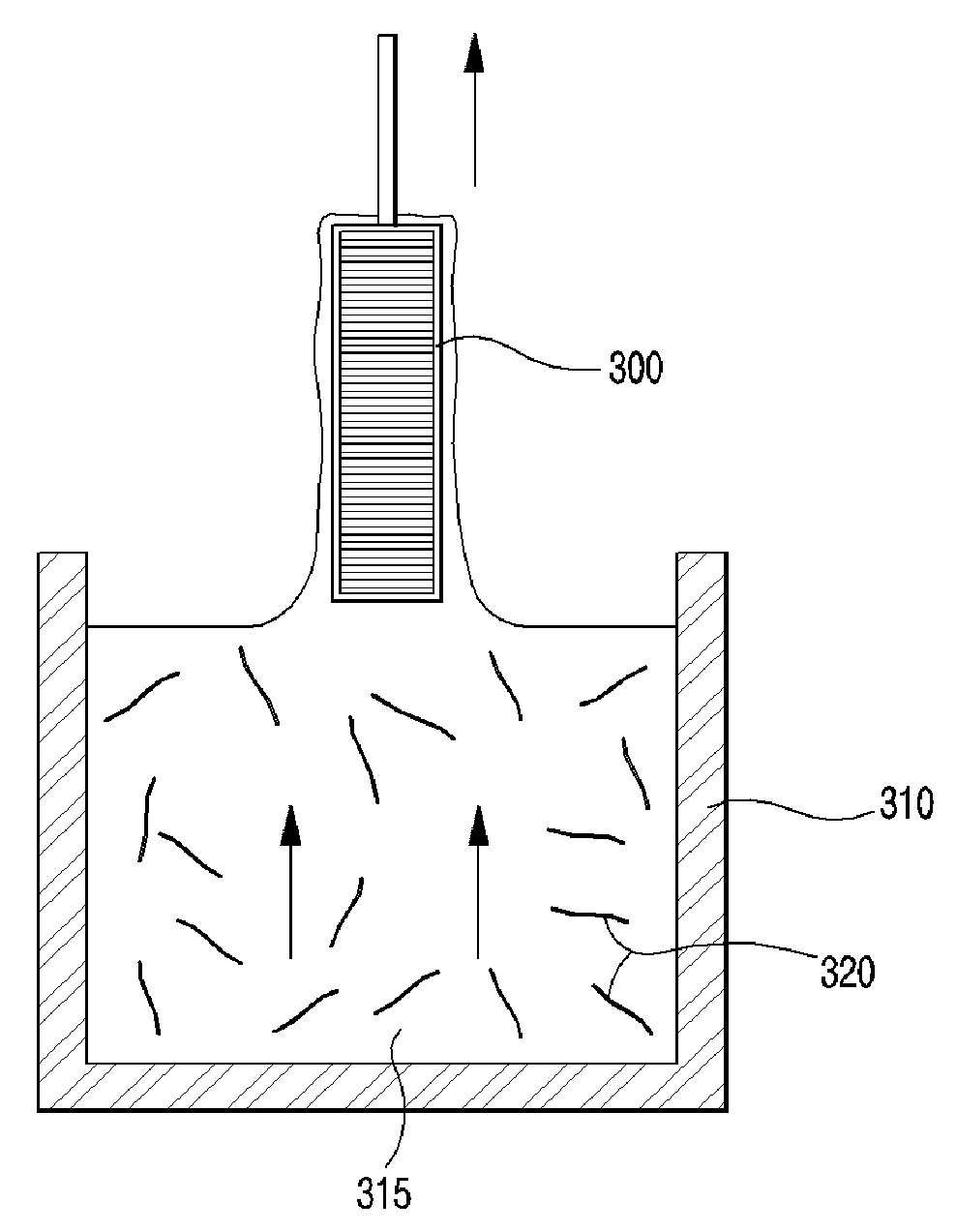
[0024]FIG. 3 illustrates the surface of the cooling fin after a cooling device including a plurality of cooling fins is formed and a dip coating process is performed on the cooling device. In one embodiment, since carbon nanotubes are formed on the surface of the cooling fin, the cooling fin can increase a contact portion for thermal exchange by several hundred times to several thousand times as compared with a conventional cooling fin having a plane structure. Also, the carbon...


PUM

PropertyMeasurementUnit
temperatureaaaaaaaaaa
lengthaaaaaaaaaa
diameteraaaaaaaaaa

Abstract

Provided are a cooling device coated with carbon nanotubes and method of manufacturing the same. Carbon nanotubes are dispersively coated on a surface of the cooling device that radiates generated by a predetermined apparatus or component through thermal exchange. Thus, a carbon nanotube structure is formed so that the cooling device can improve in a thermal radiation characteristic and become small-sized. As a result, electronic devices can be downscaled and heat generated by a highly integrated electronic circuit chip can be effectively radiated, thus increasing lifetime and performance of an operating circuit.

Description

TECHNICAL FIELD[0001]The present invention relates to a cooling device and method of manufacturing the same, and more particularly, to a cooling device in which a carbon nanotube structure is formed using a dip coating process and method of manufacturing the same.BACKGROUND ART[0002]As is well known, a high power amplifier (APM) and linear power amplifier (LPA) for a mobile communication relay, a central processing unit (CPU) for a personal computer (PC), a multiple processing unit (MPU) for a server-level workstation, and a power amplifier unit (PAU) for a relay base station are electronic components that generate a lot of heat. When the electronic components operate under breaking load, their surface temperatures are elevated and they are overheated due to generated heat. Thus, there is a strong possibility of causing malfunction and breakage of the components.[0003]In order to prevent the malfunction and breakage of the components, a device of radiating heat from electronic appar...

Claims


Application Information

Patent Timeline
Patent Type & Authority Applications(United States)
IPC IPC(8): H05K7/20B05D1/18
CPCH05K7/20427B82Y30/00C01B2202/28C01B32/158
Inventor KIM, YONG-HYUPLEE, HO-YOUNGLEE, SEUNG-MINSUNG, WOO-YONGKANG, TAE-JUNKIM, WAL-JUNYOON, JANG-WONYEON, SUN-CHANG
Owner KIM YONG HYUP
Why Eureka
Try Eureka