Diversity device

Inactive Publication Date: 2009-03-05
SHARP KK
View PDF8 Cites 7 Cited by
  • Summary
  • Abstract
  • Description
  • Claims
  • Application Information

AI Technical Summary

Benefits of technology

[0012]As discussed above, the smaller first gain the signal converter means has, the higher level the electric wave signal, which is received via the input terminal, has. Further, the higher level the electric wave signal has, the better reception condition the electric wave signal, which is received via the input terminal, has. This is because the higher level the electric wave signal has, the higher electric field strength the electric wave, which reaches the input terminal, has. The diversity device of the present invention causes first gains of the signal converter means to be compared and then the output signal that is supplied from the signal converter means having the smallest first gain to be selected. This enables selection of the electric wave signal received via the input terminal that has the best reception condition.
[0013]The comparing means included in the diversity device of the present invention is so arranged as to compare first gains of the signal converter means and to control the selecting means. This allows fabrication of the comparing means with use of a general-purpose circuit, i.e. a simple logic circuit or the like. Consequently, the diversity device of the present invention does not require a complex circuit that detects and compares the CN ratios of electric wave signals received via the input terminal or of output signals supplied from the signal converter means. This makes it possible to downsize the diversity device.

Problems solved by technology

Unfortunately, the diversity device disclosed in Patent Document 1 requires a complex circuit configuration for detecting the CN ratios of the intermediate frequency signals.
This causes a problem that the diversity device cannot be downsized.
This also causes a problem that the diversity device of Patent Document 2 cannot be downsized.

Method used


Image

  • Diversity device
  • Diversity device
  • Diversity device

Examples


first embodiment

[0025]The first embodiment of the present invention will be described in detail below with reference to FIGS. 1 and 2.

[0026](Arrangement of Diversity Device 1)

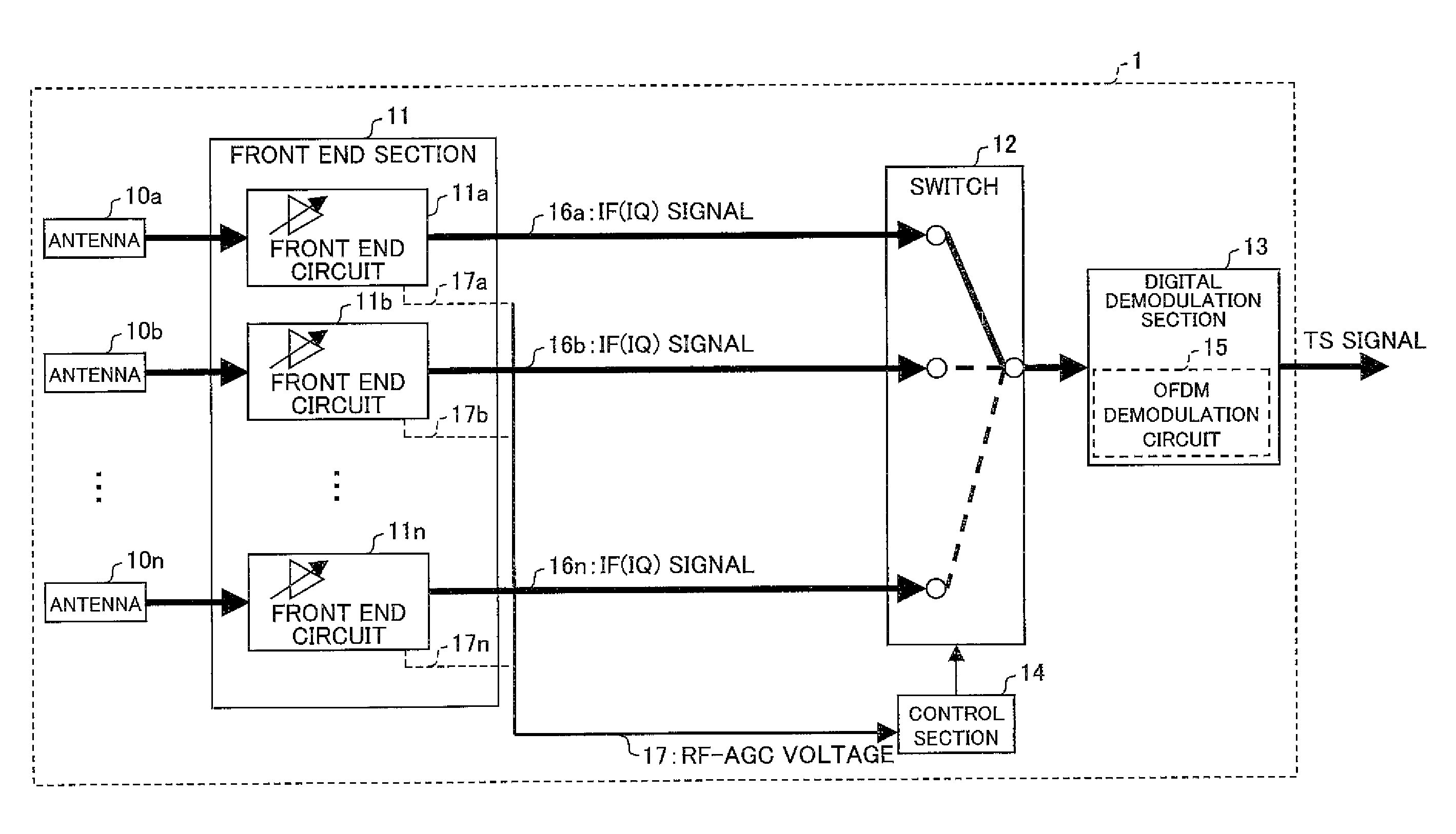
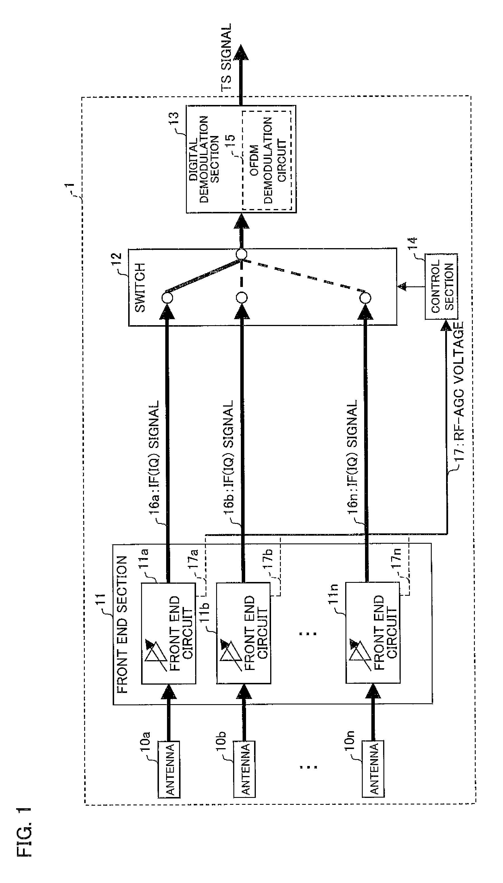
[0027]The following description deals with an arrangement of a diversity device 1 with reference to FIG. 1. FIG. 1 is a block diagram illustrating a basic arrangement of the diversity device 1 in accordance with an embodiment of the present invention.

[0028]As illustrated in FIG. 1, the diversity device 1 includes (i) a plurality of antennas 10a through 10n (hereinafter referred to as the antennas 10 when they are collectively referred to), (ii) a front-end section 11 that causes broadcast signals (electric wave signals) received via the antennas 10 (input terminals) to be subjected to amplification and frequency conversions and so that a plurality of intermediate frequency signals 16a through 16n (hereinafter referred to as the IF signals 16a through 16n, and referred to as the IF signals 16 when they are collectively referred...

second embodiment

[0056](Arrangement of Diversity Device 2)

[0057]The following describes an arrangement of a diversity device 2 of the second embodiment with reference to FIG. 3. FIG. 3 is a block diagram illustrating an arrangement of the diversity device 2 in accordance with the embodiment of the present invention.

[0058]As illustrated in FIG. 3, the diversity device 2, further to the arrangement of the first embodiment, includes intermediate frequency auto gain controls (IF-AGCs) 23a to 23n (hereinafter referred to as IF-AGCs 23 when they are collectively referred to) that amplify the IF signals 16a to 16n, respectively. According to the second embodiment, in place of the control section 14 of the first embodiment, a control section 24 (comparing means; gain comparing means) is provided that receives (a) RF-AGC voltages 17 from the front-end section 11 and (b) IF-AGC voltages 21 from the IF-AGCs 23. The switch 12 of the second embodiment receives IF signals 22a to 22n that have been subjected to am...

third embodiment

[0072](Arrangement of Diversity Device 3)

[0073]The following explains an arrangement of a diversity device 3 of the third embodiment with reference to FIG. 5. FIG. 5 is a block diagram illustrating an arrangement of the diversity device 3 in accordance with the embodiment of the present invention. It should be noted that the third embodiment explains constituent members different from those of the second embodiment, and that same members in the third embodiment as those in the second embodiment are assigned the same reference numerals and the description of the members is omitted.

[0074]As illustrated in FIG. 5, the diversity device 3, further to the arrangement of the second embodiment, includes level detection sections 32a to 32n (hereinafter referred to as level detection sections 32 when they are collectively referred to) that detect signal levels of the IF signals 16a to 16n, respectively. According to the third embodiment, in place of the control section 24 of the second embodi...


PUM


Abstract

The diversity device includes: a plurality of antennas via which electric wave signals are respectively received; and a plurality of front-end circuits for amplifying signal levels of the electric wave signals received via the plurality of antennas, respectively, target signal levels of output signals supplied from the plurality of front-end circuits being set in advance, the diversity device further including: a control section for comparing first gains of the plurality of front-end circuits; and a switch for selecting, in accordance with a comparison result obtained by the control section, an IF signal supplied from a front-end circuit, among the plurality of front-end circuits, having a smallest first gain. The above arrangement enables provision of the diversity device that is capable of (i) selecting, from among a plurality of electric wave signals, an electric wave signal which is receivable in a best condition and (ii) being downsized.

Description

[0001]This Nonprovisional application claims priority under U.S.C. §119(a) on Patent Application No. 223199 / 2007 filed in Japan on Aug. 29, 2007, the entire contents of which are hereby incorporated by reference.FIELD OF THE INVENTION[0002]The present invention relates to a diversity device capable of selecting, from among a plurality of electric wave signals received, an electric wave signal which is receivable in a best condition.BACKGROUND OF THE INVENTION[0003]The widespread use of car navigation systems in recent years has promoted the development of a diversity device, serving as a receiver for automobile use which receives digital terrestrial broadcast, which receives broadcast signals in a good condition even in a moving car.[0004]For instance, Patent Document 1 (Japanese Unexamined Patent Application Publication No. 237196 / 1994 (Tokukaihei 6-237196; published on Aug. 23, 1994)) discloses a diversity device that (i) causes broadcast signals, received via a plurality of anten...

Claims


Application Information

Patent Timeline
IPC IPC(8): H04B7/10
CPCH04L27/2647H04B7/082
Inventor KURAMOTO, SHIGEYUKI
Owner SHARP KK
Why Eureka
Try Eureka