Optical network interface devices and methods

a network interface and optical network technology, applied in the field of optical network, can solve the problems of high cost, labor-intensive replacement and upgrade of onts, and inflexible time-consuming and inflexible, and achieve the effects of reducing the number of through-wall interconnections, simplifying ont installation, and facilitating flexible ont configuration

Active Publication Date: 2009-03-05
WHITE OAK GLOBAL ADVISORS
View PDF20 Cites 72 Cited by
  • Summary
  • Abstract
  • Description
  • Claims
  • Application Information

AI Technical Summary

Benefits of technology

[0007]This disclosure is directed to devices and methods for simplifying ONT installation and facilitating flexible ONT configuration for an optical network. In accordance with some aspects of this disclosure, some of the functionality and components typically associated with an ONT may be relocated to a subscriber gateway device that resides within the subscriber premises. For example, gateway and / or optical MAC unit functionality ordinarily provided in the ONT may be relocated to the subscriber gateway device, which may result in a reduced number of through-wall interconnections. Relocation of components that perform gateway and MAC layer functionality to the subscriber gateway device within the subscriber premises may allow use of components in the subscriber gateway device that are less costly than industrial temperature rated components in the ONT located outside of the subscriber premises. Additionally, the electrical signals may be transmitted from the ONT to the subscriber gateway device via a common cable, thereby reducing the number of interconnections required between the ONT and subscriber premises and the number of wall penetrations required for installation.

Problems solved by technology

Interconnection of the ONT with subscriber devices using telephone, data, RF video and power cables can be burdensome.
As a result, ONT deployment can be costly, time-consuming and inflexible.
For example, replacement and upgrade of an ONT can be labor-intensive and present additional hardware costs.

Method used


Image

  • Optical network interface devices and methods
  • Optical network interface devices and methods
  • Optical network interface devices and methods

Examples


Embodiment Construction

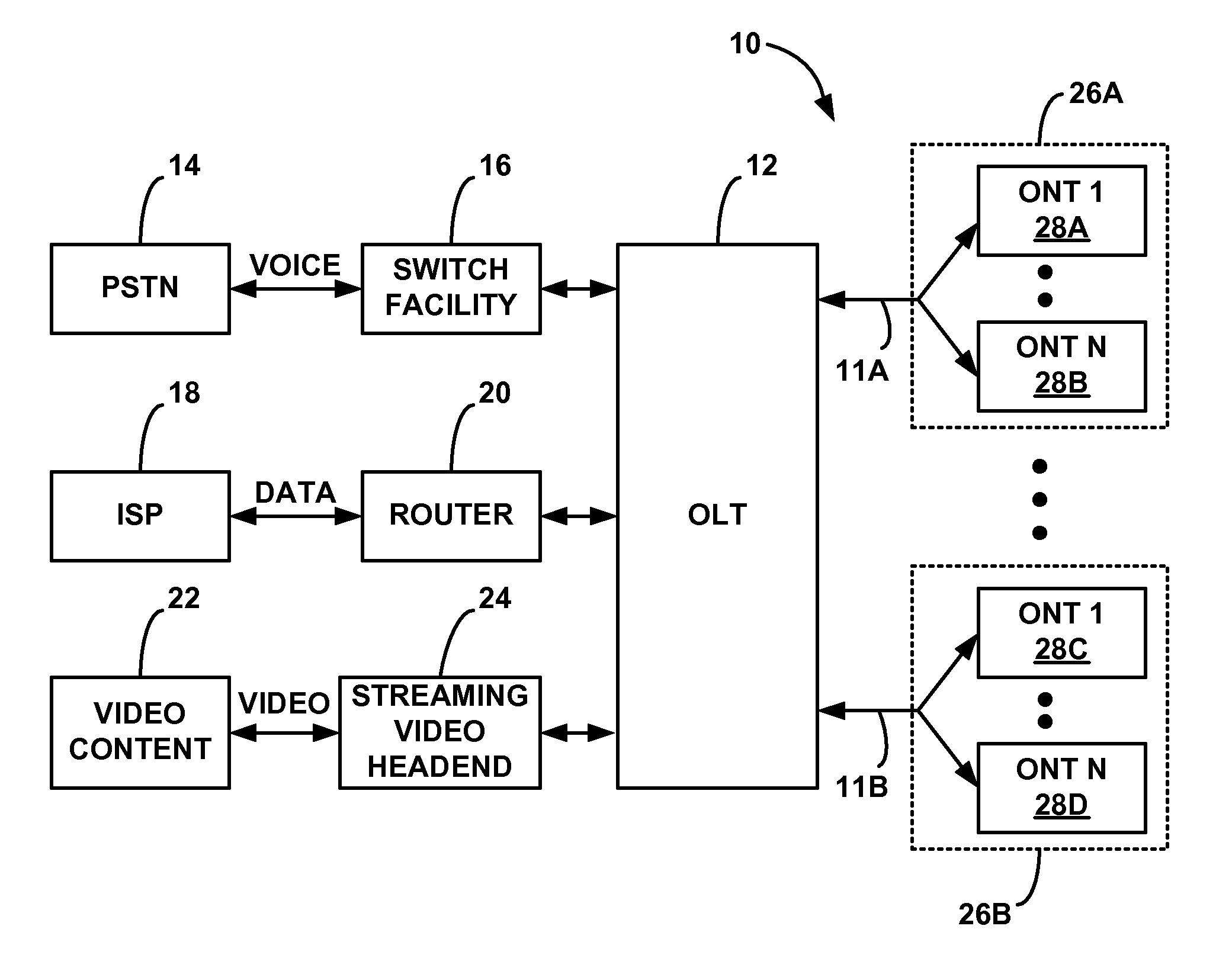
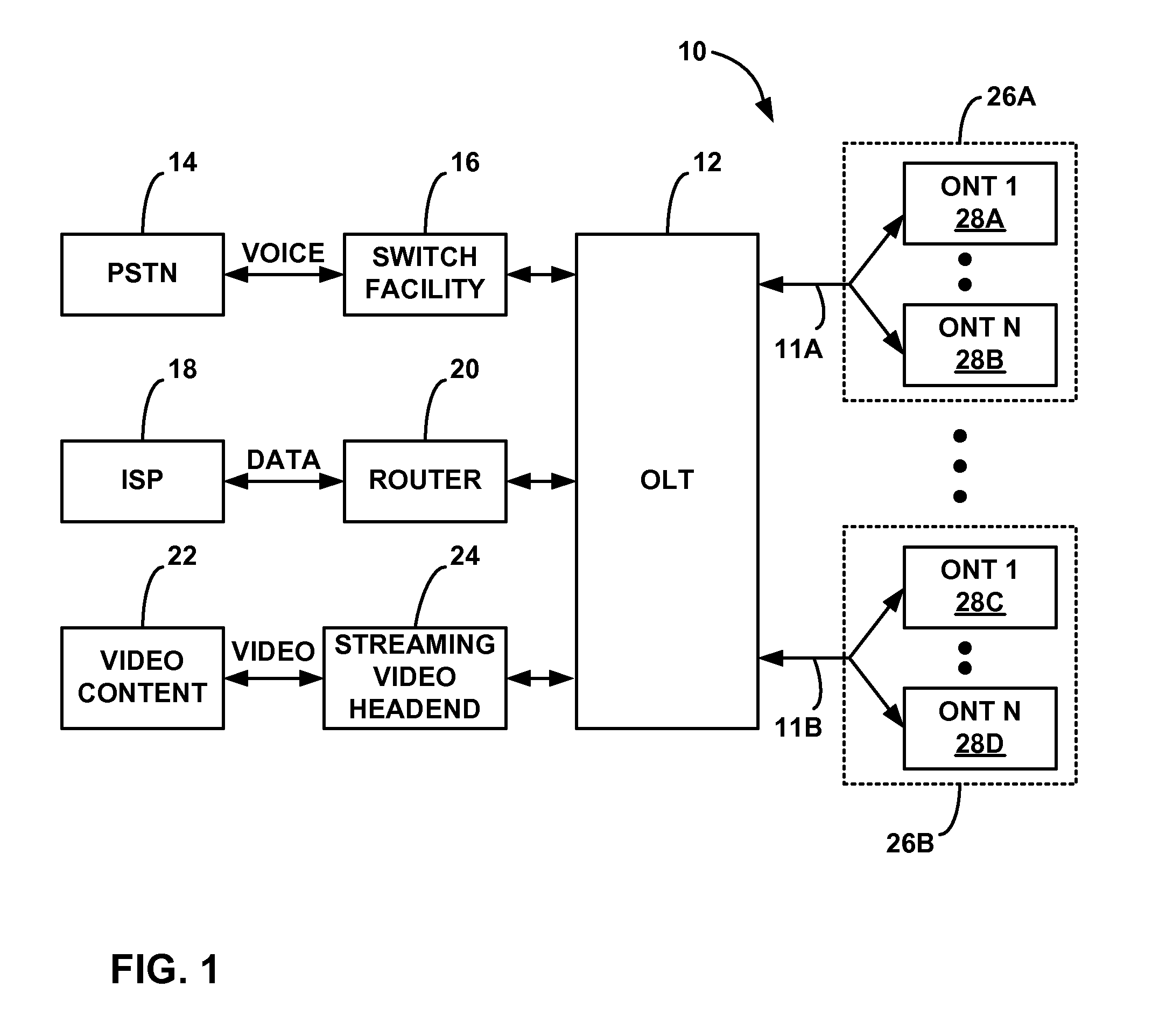
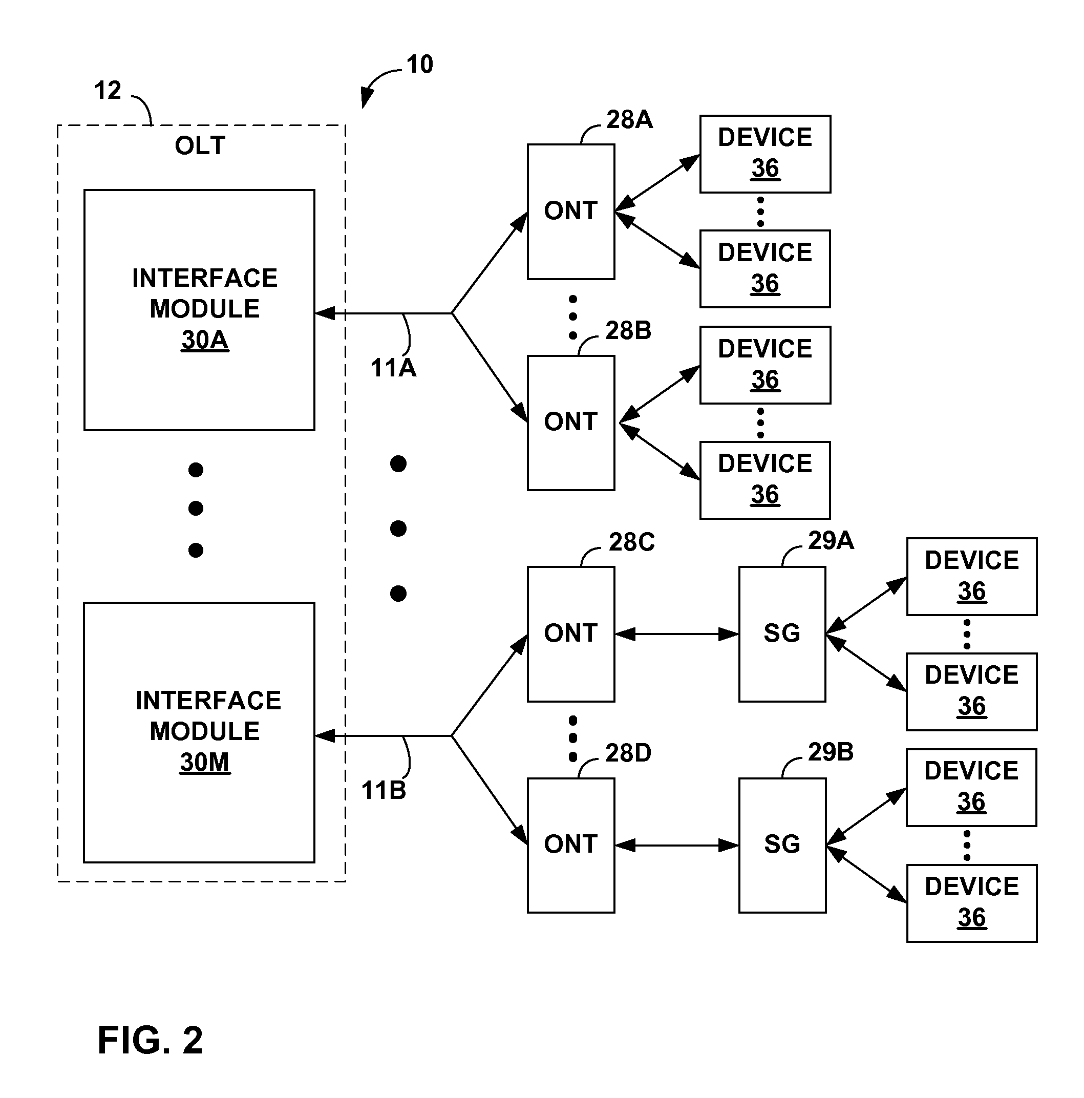
[0036]This disclosure is directed to devices and methods for simplifying optical network terminal (ONT) installation and facilitating flexible ONT configuration for an optical network. For many premises, ONT installation typically requires a technician to run multiple cables between the ONT mounted outside the premises, subscriber devices located inside the premises and / or an uninterruptible power supply (UPS) located inside the premises. For example, installation may require a telephone cable for telephone services, a data cable for data services, and an optional radio frequency (RF) cable to deliver RF video services. In addition, installation typically requires an additional power cable to connect the ONT to the UPS. This disclosure presents a number of aspects that may reduce the number of cable runs required for ONT installation and / or provide other advantages. In addition, some of the aspects may result in relocation of functionality and components from the ONT to a subscriber...


PUM


Abstract

A system comprises an optical network terminal (ONT) that provides an interface to a passive optical network (PON). The ONT is coupled to a subscriber gateway device via at least one cable. The ONT may be located outside a subscriber premises while the subscriber gateway device may be located within the subscriber premises. The ONT converts optical signals received from PON to electrical signals and transmits the electrical signals to the subscriber gateway device without performing any MAC layer functions. The subscriber gateway device includes an optical media access control (MAC) unit that converts the electrical signals into MAC layer signals and a gateway unit that distributes the MAC layer signals to one or more subscriber devices. In this manner the MAC and gateway layer functions are relocated from the ONT to the subscriber gateway device.

Description

[0001]This application claims the benefit of U.S. Provisional Application No. 60 / 969,005, filed Aug. 30, 2007, the entire content of which is incorporated herein by reference.TECHNICAL FIELD[0002]This disclosure relates to optical networks and, more particularly, network interface devices for optical networks.BACKGROUND[0003]Optical networks are used to deliver voice, data and video services to multiple network subscribers using one or more optical fibers. The optical networks deployed to deliver the voice, data and video services may be either passive or active. In a passive optical network (PON), for example, passive optical splitters and combiners enable multiple subscribers to share the same optical fiber. Thus, the PON functions as a point-to-multipoint optical network. A PON may conform to any of a variety of PON standards, such as broadband PON (BPON) (ITU G.983), gigabit-capable PON (GPON) (ITU G.984), or gigabit-capable Ethernet PON (GEPON) (IEEE 802.3). In an active optica...

Claims


Application Information

Patent Timeline
Patent Type & Authority Applications(United States)
IPC IPC(8): H04B10/06H04L12/28
CPCH04J14/0226H04J14/0282H04J14/0298H04L12/2856H04L12/2861H04J14/0232H04Q11/0067H04Q11/0071H04J14/0247H04J14/0252H04L12/2885
Inventor BIEGERT, MARK R.PAULSEN, MARK T.
Owner WHITE OAK GLOBAL ADVISORS
Why Eureka
Try Eureka