Fluid transportation device

a technology of transportation device and fluid, which is applied in the direction of machines/engines, liquid fuel engines, and positive displacement liquid engines, etc., can solve the problems of cost-intensive micro actuators, and achieve the effect of excellent flow rate and output pressure, quick opening or closing

Inactive Publication Date: 2009-03-05
MICROJET TECH
View PDF18 Cites 49 Cited by
  • Summary
  • Abstract
  • Description
  • Claims
  • Application Information

AI Technical Summary

Benefits of technology

[0008]It is an object of the present invention to provide a fluid transportation device. A valve seat, a valve membrane, a valve cap, an actuating module and a cover plate are sequentially stacked from bottom to top, thereby assembling the fluid transportation device. The actuating module is activated to deform the vibrating film and thus the volume of the pressure cavity is changed to result in a positive or negative pressure difference. In addition, the inlet / outlet valve structures of the valve membrane are quickly opened or closed. At the moment when the volume of the pressure cavity is expanded or shrunken, suction or impulse is generated to flow the fluid. The fluid transportation device of the present invention can transport gases or liquids at excellent flow rate and output pressure. By using the fluid transportation device of the present invention, the problem of returning back the fluid during fluid transportation is avoided.

Problems solved by technology

Under this circumstance, a costly micro actuator is required.

Method used


Image

  • Fluid transportation device
  • Fluid transportation device
  • Fluid transportation device

Examples


Embodiment Construction

[0023]The present invention will now be described more specifically with reference to the following embodiments. It is to be noted that the following descriptions of preferred embodiments of this invention are presented herein for purpose of illustration and description only. It is not intended to be exhaustive or to be limited to the precise form disclosed.

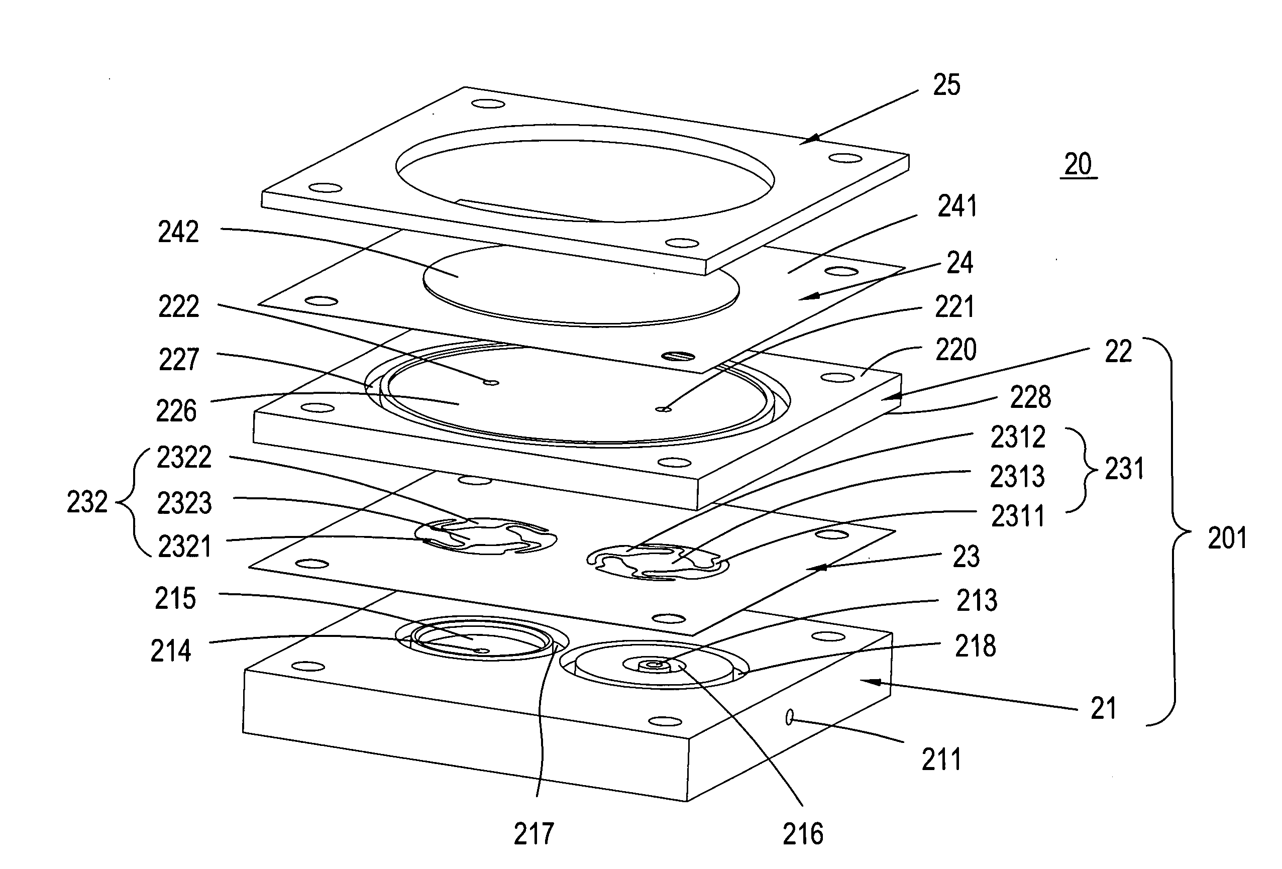
[0024]Referring to FIG. 3, a schematic exploded view of a fluid transportation device according to a first preferred embodiment of the present invention is illustrated. The fluid transportation device 20 may be used in many sectors such as pharmaceutical industries, computer techniques, printing industries, energy industries for transporting fluids such as gases or liquids. The fluid transportation device 20 principally comprises a valve seat 21, a valve cap 22, a valve membrane 23, several buffer chambers, an actuating module 24 and a cover plate 25. The valve seat 21, the valve cap 22 and the valve membrane 23 collectively defi...


PUM


Abstract

A fluid transportation device includes a valve seat, a valve cap, a valve membrane, multiple buffer chambers, a vibration film and an actuator. The valve membrane is arranged between the valve seat and the valve cap, and includes several hollow-types valve switches, which includes at least a first valve switch and a second valve switch. The multiple buffer chambers include a first buffer chamber between the valve membrane and the valve cap and a second buffer chamber between the valve membrane and the valve seat. The vibration film is separated from the valve cap when the fluid transportation device is in a non-actuation status, thereby defining a pressure cavity. The actuator is connected to the vibration film. When the actuator is driven to be subject to deformation, the vibration film connected to the actuator is transmitted to render a volume change of the pressure cavity and result in a pressure difference for moving the fluid.

Description

FIELD OF THE INVENTION[0001]The present invention relates to a fluid transportation device, and more particularly to a fluid transportation device for use in a micro pump.BACKGROUND OF THE INVENTION[0002]Nowadays, fluid transportation devices used in many sectors such as pharmaceutical industries, computer techniques, printing industries, energy industries are developed toward miniaturization. The fluid transportation devices used in for example micro pumps, micro atomizers, printheads or industrial printers are very important components. Consequently, it is critical to improve the fluid transportation devices.[0003]FIG. 1A is a schematic cross-sectional view illustrating a micro pump in a non-actuation status. The micro pump 10 principally comprises an inlet channel 13, a micro actuator 15, a transmission device 14, a diaphragm 12, a compression chamber 111, a substrate 11 and an outlet channel 16. The compression chamber 111 is defined between the diaphragm 12 and the substrate 11...

Claims


Application Information

Patent Timeline
Patent Type & Authority Applications(United States)
IPC IPC(8): F04B49/00
CPCF04B43/043F04B43/046F04B53/10F05B2210/11F05B2260/60Y10S417/00
Inventor CHEN, SHIH CHANGCHENG, CHIANG HOYU, RONG HOTSAI, JYH HORNGCHIU, SHIH CHE
Owner MICROJET TECH
Why Eureka
Try Eureka