Fuel injection device

a fuel injection device and fuel injection technology, applied in the direction of fuel injecting pumps, liquid fuel feeders, machines/engines, etc., can solve the problem of not being able to be actuated by piezoelectric actuators, etc., and achieve the effect of short device structure length and large valve cross section

Inactive Publication Date: 2007-11-06
ROBERT BOSCH GMBH
View PDF16 Cites 11 Cited by
  • Summary
  • Abstract
  • Description
  • Claims
  • Application Information

AI Technical Summary

Benefits of technology

[0006]The fuel injection system of the invention for internal combustion engines has the advantage over the prior art that a common rail injector with a piezoelectric actuator is created, in which a large cross section of the valve is possible. As a result, the opening and closing of the injection valve can be effected faster. The integrated coupler makes a short structural length of the device possible. The coupler is reinforced by CR pressure.

Problems solved by technology

This valve can be embodied with only a relatively small diameter, since otherwise the forces on the valve become too high, so that it cannot be actuated by a piezoelectric actuator.

Method used


Image

  • Fuel injection device
  • Fuel injection device

Examples


Embodiment Construction

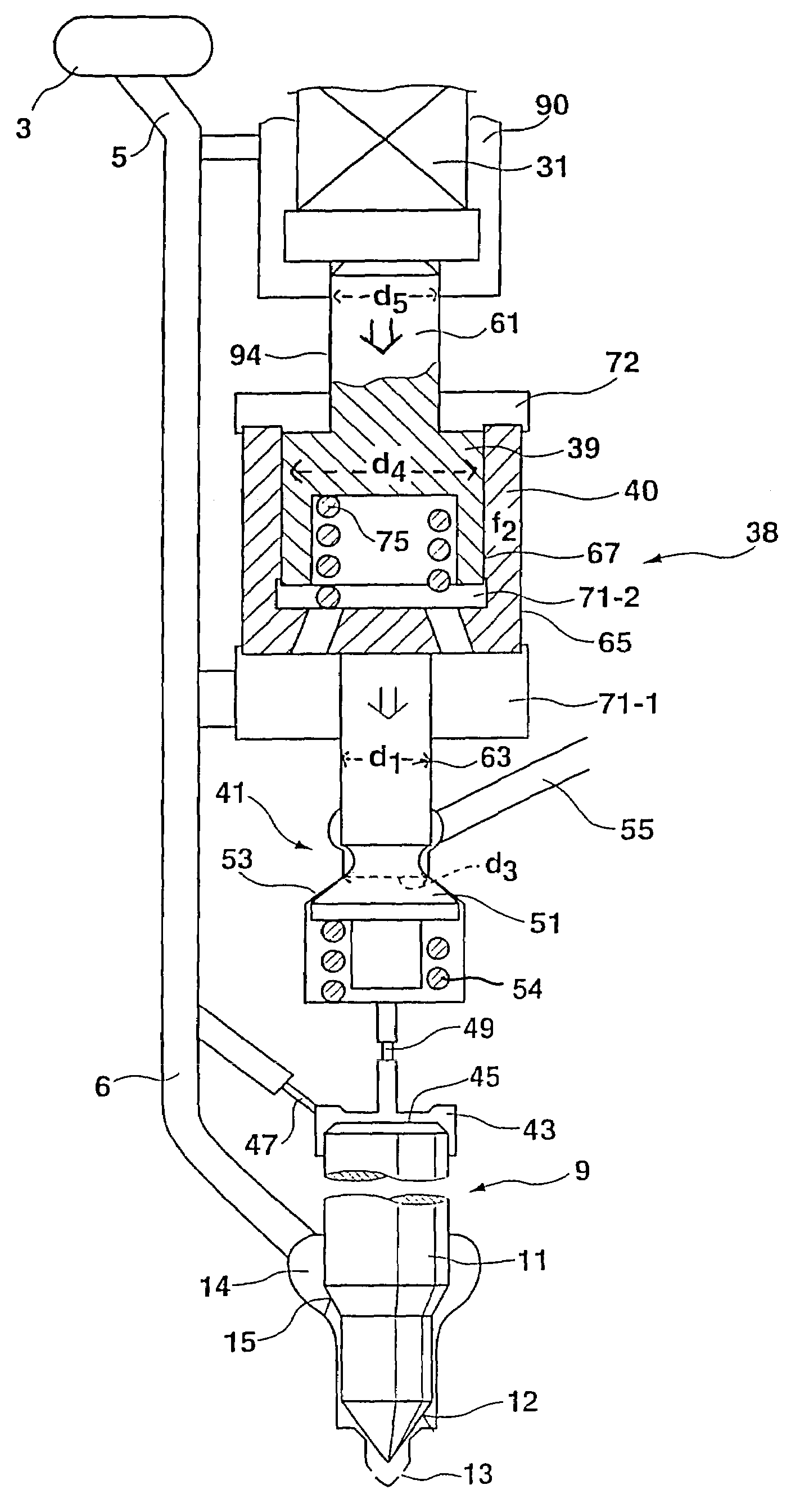
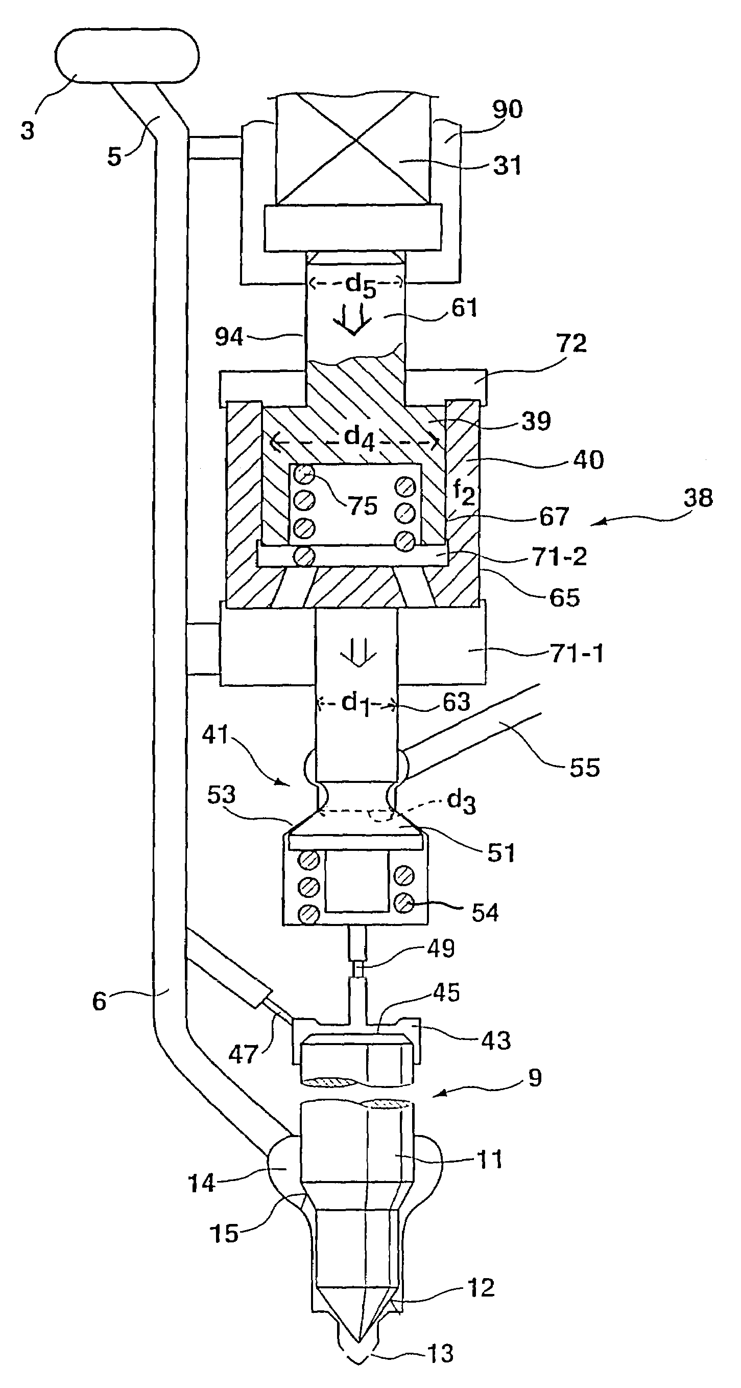
[0008]The fuel injection system of the invention is supplied with fuel at high pressure by a pressure reservoir (common rail) 3 via a high-pressure line 5, from which fuel flows via an injection line 6 to reach an injection valve 9. An internal combustion engine normally has several such injection valves, and for the sake of simplicity only one is shown. The injection valve 9 has a valve needle (valve piston, nozzle needle) 11, which in its closing position, with a conical valve sealing face 12, closes injection openings 13 through which fuel is to be injected into the interior of a combustion chamber of the engine. The fuel reaches the vicinity of the nozzle needle via an annular nozzle chamber 14, from which, via a control face 15 embodied as a pressure shoulder, it makes it possible to exert a pressure in the opening direction of the nozzle needle. When this pressure exerts a force in the opening direction on the valve needle that overcomes forces acting counter to this opening, ...


PUM


Abstract

A fuel injection system having an injection valve, a line supplying fuel at high pressure to the injection valve a control valve controlling the pressure in a control chamber communicating with the line. The control valve has a movable valve part is actuatable by an actuator via a hydraulic coupler having two pistons cooperating with a booster chamber of the coupler. A seat of the movable valve part has an inside cross-sectional area f3, with means for filling the booster chamber via guide gaps of the pistons with fuel under pressure. The pistons are located parallel to and inside one another and a booster chamber is located on the ends of the pistons toward the actuator. In the interior of the outer piston defines a filling chamber which communicates with the line and one of the pistons has a cross-sectional area f4 is mechanically coupled to the actuator via a rod having a cross-sectional area f5. The other piston which has a piston area f2, actuates the control valve via a rod having a cross-sectional area that is smaller than f2 and the direction of the closing motion of the movable valve part matches the direction of fuel flowing out of the control chamber so that the control valve is at least partially force-balanced because of the pressure acting on the further piston in the booster chamber.

Description

CROSS-REFERENCE TO RELATED APPLICATIONS[0001]This application is a 35 USC 371 application of PCT / DE 2004 / 001200 filed on Jun. 9, 2004.BACKGROUND OF THE INVENTION[0002]1. Field of the Invention[0003]The invention is directed to an improved fuel injection system for an internal combustion engine.[0004]2. Description of the Prior Art[0005]A common rail injector (hereinafter. CR stands for “common rail”) with a piezoelectric actuator (or piezoelectric controller) and with boosting by hydraulic couplers is known. Integrated couplers with pistons disposed coaxially inside one another are also known. One known device uses an outward-opening valve as a control valve. This valve can be embodied with only a relatively small diameter, since otherwise the forces on the valve become too high, so that it cannot be actuated by a piezoelectric actuator.SUMMARY AND ADVANTAGES OF THE INVENTION[0006]The fuel injection system of the invention for internal combustion engines has the advantage over the p...

Claims


Application Information

Patent Timeline
Patent Type & Authority Patents(United States)
IPC IPC(8): F02M37/04F02M47/02F02M59/46F02M61/16F02M63/00F02M63/02
CPCF02M47/027F02M63/0026F02M63/0073F02M61/167F02M63/004F02M2200/705F02M63/0225F02M2200/703F02M2200/704F02M63/0043
Inventor BOECKING, FRIEDRICH
Owner ROBERT BOSCH GMBH
Why Eureka
Try Eureka