Double-peak-voltage holding high-speed solenoid valve drive circuit

A high-speed solenoid valve and drive circuit technology, applied in the direction of electromagnets, electromagnets with armatures, valve details, etc., can solve the problem of poor discharge of the induced voltage of the low-end drive circuit, affecting the life of the low-end drive circuit, not applicable High-frequency applications and other problems, to achieve the effect of solving the problem of poor induction voltage discharge, realizing multi-channel solenoid valve driving, and reducing the load of microprocessors

Inactive Publication Date: 2007-05-23
上海凌同电子科技有限公司 +1
View PDF0 Cites 11 Cited by
  • Summary
  • Abstract
  • Description
  • Claims
  • Application Information

AI Technical Summary

Problems solved by technology

[0005] (1) The design is complex and the cost is high;
[0006] (2) The microprocessor is often required to participate in the peak hold process, which increases the load on the microprocessor;
[0007] (3) It solves the problem of continuous flow and removal of induced voltage spikes when the solenoid valve is turned off, but the valve closing time is still long, which is not suitable for high-frequency applications;
[0008] (4) A rectifier diode is connected in series at the output end of the low-end drive circuit to prevent the high-end drive voltage from feeding back. This has no effect on the solenoid valve freewheeling and the removal of induced voltage peaks, but it does not allow the induced voltage of the low-end drive circuit to discharge. Smooth, affecting the life of the low-end drive circuit

Method used


Image

  • Double-peak-voltage holding high-speed solenoid valve drive circuit
  • Double-peak-voltage holding high-speed solenoid valve drive circuit
  • Double-peak-voltage holding high-speed solenoid valve drive circuit

Examples


Embodiment Construction

[0029] The concrete implementation of the present invention will be further described below in conjunction with accompanying drawing:

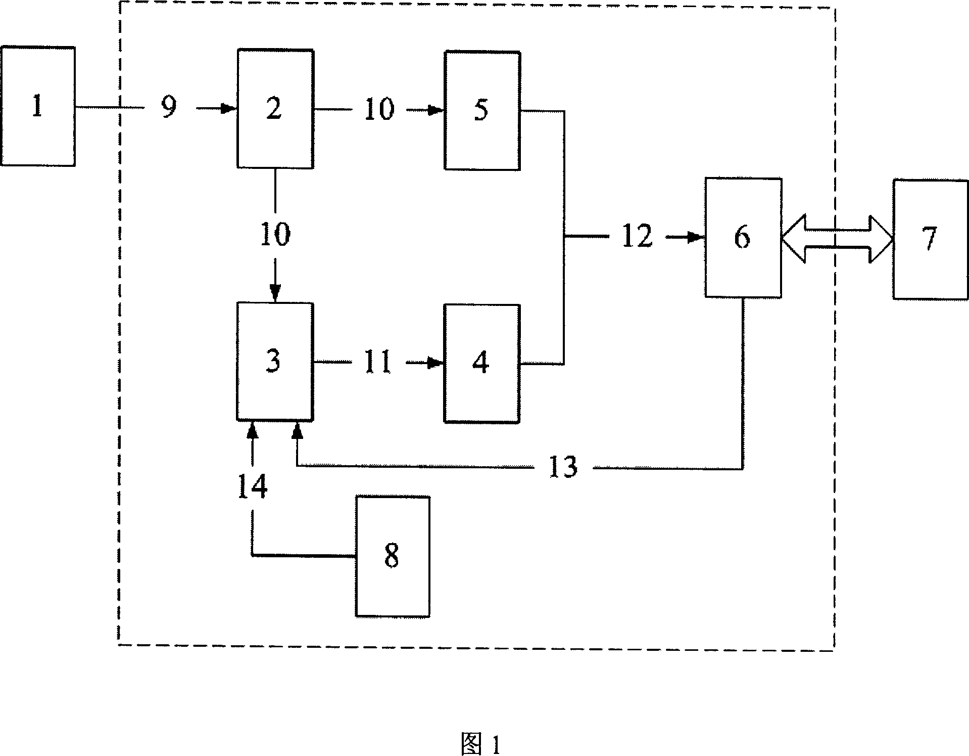
[0030] Figure 1 shows the structural block diagram of the dual-voltage peak hold high-speed solenoid valve drive circuit. The structure shown in the dotted line box is the structure of the device, including the isolation circuit 2, the high-end current limiting circuit 3, the high-end drive circuit 4, and the low-end drive circuit. Circuit 5, peak removal and current detection circuit 6 and peak current setting circuit 8. The input end of the isolation circuit 2 is connected to the output end of the valve controller 1, and its output end is the isolated valve control pulse, which is respectively connected to the input ends of the high-end current limiting circuit 3 and the low-end drive circuit 5; the high-end current limiting circuit 3 The output end of the circuit is connected with the high-end drive circuit 4, and outputs a high level when ...


PUM


Abstract

It relates to the dual voltage peak valve retaining driving circuit. It uses parallel dual voltage drive. The low end drive circuit keeps conducting when the control pulse arrives, high end drive circuit conducts with the rising of control pulse, cutting off the flow limit circuit made of simple separated units when the drive current reaches preset peak valve, and the electromagnetic drive circuit entering into the only existing low end drive circuit retaining stage. With bleed resistance on the low end drive circuit, it can solve the problem of instant unable to follow up of the low end drive circuit with the leakage of electromagnetic valve and high end electric circuit with instant cut off of the electromagnetic valve. On the after-flow of the electromagnetic valve, adopting parallel voltage sensitive resistance to get rid of the sensing voltage peak occurring at the instant of the electromagnetic valve cut-off, it not only get rid of the sensing voltage peak, but also ensures the cut-off speed of the valve. It is quick, endurable and extensively applicable.

Description

technical field [0001] The invention belongs to a driving circuit for a solenoid valve, in particular to a driving circuit for a high-speed solenoid valve with dual-voltage peak holding. Background technique [0002] The execution of the solenoid valve action is realized by controlling its driving current, and for a specific driving circuit, the driving strategy directly determines the change of the driving current. Therefore, the requirements for the performance of the solenoid valve will eventually be realized through a specific driving strategy. There are two main objectives for the optimization of solenoid valve actuation: energy consumption and response time. In high-frequency applications, reducing unnecessary solenoid valve drive loss is of great significance to reduce system power consumption. Response time refers to the time interval from when the solenoid valve coil is energized to when the solenoid valve stem completes a certain action, such as the time interval...

Claims


Application Information

Patent Timeline
Patent Type & Authority Applications(China)
IPC IPC(8): F16K31/06H01F7/18
Inventor 朱元刘蒙吴志红陈宏
Owner 上海凌同电子科技有限公司
Why Eureka
Try Eureka