Belt transmission device

a transmission device and belt technology, applied in mechanical equipment, gearing, hoisting equipment, etc., can solve the problems of affecting the transmission of belts, and preventing the frictional engagement of drive belts with driven pulleys, so as to increase the transmission loss and reduce the friction between the drive belt and the driven pulley. the effect of high friction coefficien

Active Publication Date: 2009-03-05
BANDO CHEM IND LTD
View PDF9 Cites 20 Cited by
  • Summary
  • Abstract
  • Description
  • Claims
  • Application Information

AI Technical Summary

Benefits of technology

[0015]According to the belt drive system of the present invention in which torque from the drive pulley for the drive source is transmitted via the drive belt to the driven pulley for the driven unit and torque of the driven pulley is transmitted to the driven unit via the joint for stopping the torque transmission when receiving an overload, when a slip corresponding to an overload of the joint occurs between the drive belt and the driven pulley, the coefficient of friction between the drive belt and the driven pulley becomes high, which ensures that the joint operates to stop the torque transmission without previously unnecessarily increasing the coefficient of friction between the drive belt and the driven pulley or the belt tension. As a result, when one of the driven units malfunctions, torque transmission to the other driven units can be maintained without incurring production of abnormal sound due to excessively high coefficient of friction between the drive belt and the driven pulley or increase in transmission loss due to excessively high belt tension.

Problems solved by technology

However, the drive belt does not stop frictional engagement with the driven pulley.
This impedes the traveling of the drive belt, which may inhibit appropriate torque transmission to the other accessories or may break the drive belt.

Method used


Image

  • Belt transmission device
  • Belt transmission device
  • Belt transmission device

Examples


Embodiment Construction

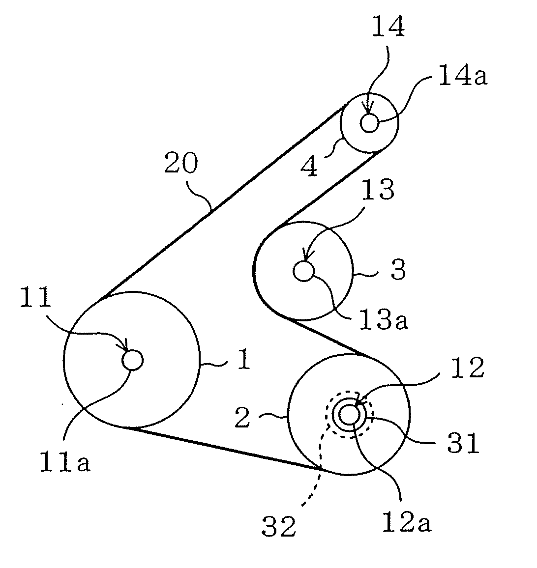
[0027]FIG. 1 schematically shows the overall structure of a belt accessory drive system for a vehicle engine according to an embodiment of the present invention. The structure of the accessory drive system is called a serpentine layout in which a single V-ribbed belt 20 serving as a drive belt is wrapped in a serpentine form around a crank pulley 1 serving as a drive pulley, a compressor pulley 2 for an air conditioner, a water pump pulley 3 and an alternator pulley 4.

[0028]Specifically, the crank pulley 1 is connected to a crank shaft 11a of an engine 11 for unitary rotation. The compressor pulley 2 is mounted coaxially on an input shaft 12a of a compressor 12. The water pump pulley 3 is connected to an input shaft 13a of a water pump 13 for unitary rotation. The alternator pulley 4 is connected to an input shaft 14a of an alternator 14 for unitary rotation. The crank pulley 1, the compressor pulley 2 and the alternator pulley 4 are V-ribbed pulleys having a plurality of circumfere...


PUM

PropertyMeasurementUnit
pitch lengthaaaaaaaaaa
pressing forceaaaaaaaaaa
torqueaaaaaaaaaa

Abstract

[Purpose] A belt drive system, in which a drive belt 20 is wrapped between a drive pulley 1 drivingly connected to a drive source 11 and a driven pulley 2 connected to an driven unit 12 via a joint 32 provided to stop torque transmission when receiving a load equal to or over a predetermined value and torque is transmitted via the drive belt 20 from the drive pulley 1 to the driven pulley 2, ensures that when the driven unit 12 malfunctions, the joint 32 stops the torque transmission without unnecessarily increasing the coefficient of friction against the driven pulley 2 or the belt tension.
[Solution] The belt drive system is configured so that when a slip corresponding to the load on the joint 32 equal to or over the predetermined value occurs between the drive belt 20 and the driven pulley 2, the coefficient of friction between the drive belt 20 and the driven pulley 2 becomes higher than that before the slip occurs.

Description

TECHNICAL FIELD[0001]This invention relates to belt drive systems in which, in transmitting torque via a single drive belt to a plurality of driven units, torque transmission to a disabled driven unit is stopped and torque transmission to the other driven units is thereby maintained, and particularly relates to measures for ensuring the stop of torque transmission to the disabled driven unit.BACKGROUND ART[0002]For example, serpentine belt accessory drive systems for vehicle engines are each configured to transmit torque to a plurality of accessories to drive them by wrapping a single drive belt around a crank pulley of the engine and driven pulleys for the accessories.[0003]In such a case, if one of the accessories is disabled and goes down, the brake will be applied to the rotation of the driven pulley for the disabled accessory. However, the drive belt does not stop frictional engagement with the driven pulley. This impedes the traveling of the drive belt, which may inhibit appro...

Claims


Application Information

Patent Timeline
Patent Type & Authority Applications(United States)
IPC IPC(8): F16H7/02F16H35/10
CPCF16H35/10F16G5/04Y10T74/19847F16H7/02F16G5/20
Inventor HAYASHI, TAKEHIRO
Owner BANDO CHEM IND LTD
Why Eureka
Try Eureka