
Clip-Like Implant for Osteosynthesis

a technology of osteosynthesis and implant, which is applied in the direction of staples, nails, diagnostics, etc., can solve the problems of not providing sufficient fixing of repositioned bone fragments, and achieve the effects of reducing the dimensions of the clip-like implant, facilitating surgical operation, and facilitating the repositioning of bone fragments

Inactive Publication Date: 2009-03-05
SHANO MAJID
View PDF14 Cites 28 Cited by
  • Summary
  • Abstract
  • Description
  • Claims
  • Application Information

AI Technical Summary

Benefits of technology

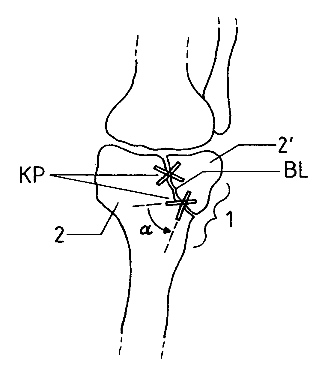
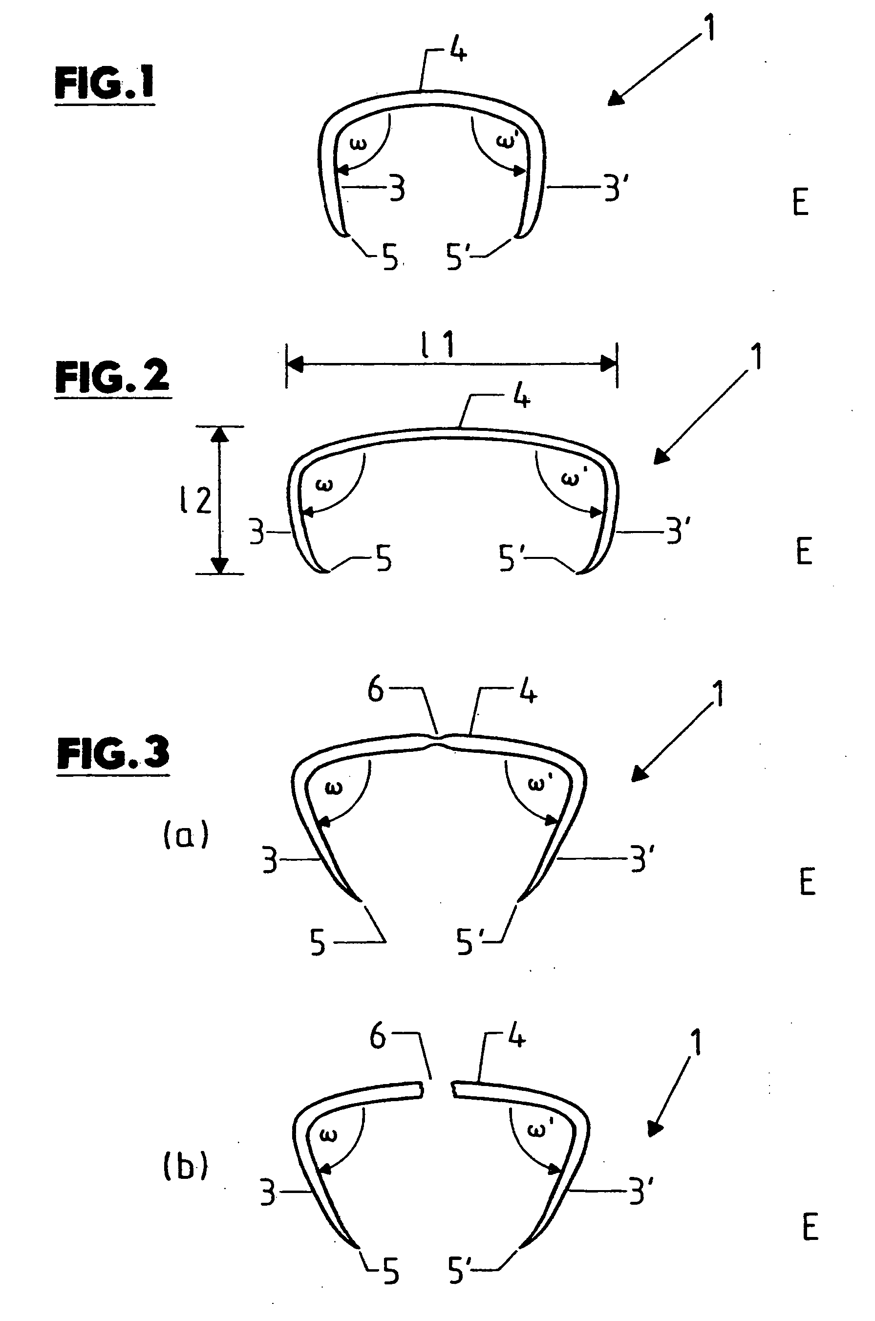
[0005]The essential aspects of the clip-like implant for osteosynthesis according to the invention are that the clip-like implant has a C-shaped cross section, the first and second retainer web section enclose with the respective connection web section an angle between 75° and 90° and the free ends of the at least two retainer web sections are designed as inwardly directed points. Advantageously, the clip-like implant can be fixed in the respective bone fragment by means of simple surgical instruments, in particular by driving the free ends of the at least two retainer web sections designed as points into the two opposing bone fragments, to stabilize the latter after repositioning. Due to the significantly reduced dimensions of the clip-like implant as compared with conventional plate implants, several implants can be surgically inserted via one small surgical opening, for example, thus also enabling treatment of large-surface fractures. The clip-like implants according to the invention can be manufactured inexpensively and can be driven into the bone fragments to be stabilized using a considerably simplified surgical procedure. Especially advantageously, the stability of the fixation is increased by the fact that due to the C-shaped design of the clip-like implant according to the invention, the inwardly directed points at least partially grip behind the bone wall.

Problems solved by technology

The disadvantage of such clip-like implants is that they do not provide sufficient fixing of the repositioned bone fragments for treatment of complicated first and second degree bone fractures, especially in the case of dynamic stress on the fixed bone fragments.

Method used


Image

  • Clip-Like Implant for Osteosynthesis
  • Clip-Like Implant for Osteosynthesis
  • Clip-Like Implant for Osteosynthesis

Examples


Embodiment Construction

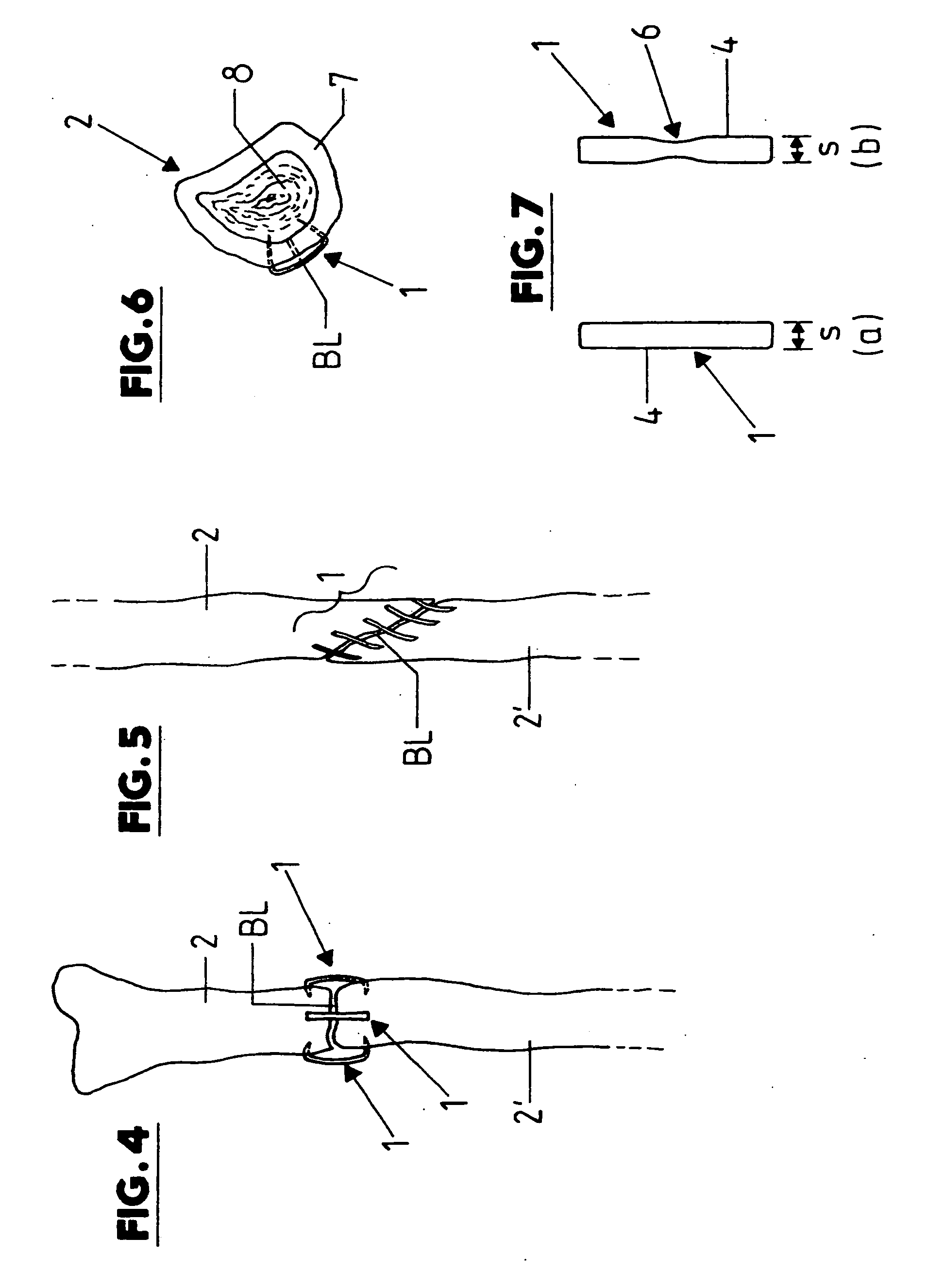
[0017]In the drawings, 1 generally designates the clip-like implant according to the invention, which is intended for osteosynthesis of at least two repositioned bone fragments 2, 2′, i.e. bone fragments that have been moved into the correct anatomical position.

[0018]The implant 1 preferably has a C-shaped cross section and comprises at least one first and second retainer web section 3, 3′ and at least one connection web section 4 of a different thickness S (see FIGS. 1, 2, 3 and 8) connecting the two retainer web sections 3, 3′.

[0019]The connection web section 4 is preferably straight or rod-shaped or slightly curved and merges at its two ends into the first and second retainer web section 3, 3′ with an form-fit. The two retainer web sections 3, 3′ each stick out in the same direction from the connecting web section 4 and each have a point 5, 5′ on their free ends. The first and second retainer web sections 3, 3′ each enclose with the connection web section 4 in the plane E an angl...


PUM


Abstract

The invention relates to a clip-like implant for osteosynthesis of at least two repositioned bone fragments, with at least two retainer web sections and with one connection web section connecting the retainer web sections, wherein the free ends of the at least two retainer web sections can be at least partially fixed in a respective one of the two repositioned bone fragments. Advantageously the clip-like implant has a C-shaped cross section, in which the first and second retainer web sections each enclose with the connection web section an angle (w, w′) between 75° and 90°, and the free ends of the at least two retainer web sections are designed as inwardly directed points.

Description

BACKGROUND OF THE INVENTION[0001]The invention relates to a clip-like implant for osteosynthesis of at least two repositioned bone fragments.[0002]Clip-like implants for the surgical joining of repositioned bone fragments (“osteosynthesis”) are known in the art, for example from US 2003 / 0139746 and U.S. Pat. No. 5,053,038, which can be used to stabilize at least two repositioned bone fragments in the anatomically correct position, in particular within the framework of osteosynthesis performed subsequent to surgical sectioning of bone (“osteotomy”).[0003]The disadvantage of such clip-like implants is that they do not provide sufficient fixing of the repositioned bone fragments for treatment of complicated first and second degree bone fractures, especially in the case of dynamic stress on the fixed bone fragments.[0004]It is an object of the invention is to present a clip-like implant for osteosynthesis by means of which at least two repositioned bone fragments can be sufficiently fix...

Claims


Application Information

Patent Timeline
IPC IPC(8): A61B17/04
CPCA61B17/0642A61B17/0644A61B2019/307A61B17/92A61B17/16A61B2090/037
Inventor SHANO, MAJID
Owner SHANO MAJID
Learn More