Driving-force distribution control device

a technology of driving force distribution and control device, which is applied in the direction of control device, vehicle components, instruments, etc., can solve the problems of unstabilized control, fine reduction control matching, and inability to finely distribute driving force on the intermediate road

Inactive Publication Date: 2009-03-05
MITSUBISHI MOTORS CORP
View PDF4 Cites 11 Cited by
  • Summary
  • Abstract
  • Description
  • Claims
  • Application Information

AI Technical Summary

Benefits of technology

[0012]According to one aspect of the invention, there is provided a driving-force distribution control device including: a distributing mechanism operable to variably distribute a driving force from an engine to individual drive wheels of a vehicle; a distribution controller operable to control the distributing mechanism based on a running state of the vehicle; an anti-skid brake system activated when the vehicle is braked so as to control braked states of the individual wheels thereby controlling slipping states of the individual wheels; an ac...

Problems solved by technology

Here, the vehicle having both the aforementioned driving-force distributing system and the ABS is troubled by a problem that the control by the driving-force distributing mechanism and the control by the ABS interfere.
Therefore, the technique raises a problem that the driving force cannot be finely distributed on the intermediate μ road (e.g., the wet asphalt road surface or the unpaved road), on a snow road of the low-μ road, or on an extremely low-μ road (e.g., a frozen road or on the ice).
In case the road surfa...

Method used


Image

  • Driving-force distribution control device
  • Driving-force distribution control device
  • Driving-force distribution control device

Examples


Embodiment Construction

[0016]A driving-force distribution control device according to one exemplary embodiment of the present invention is described in the following.

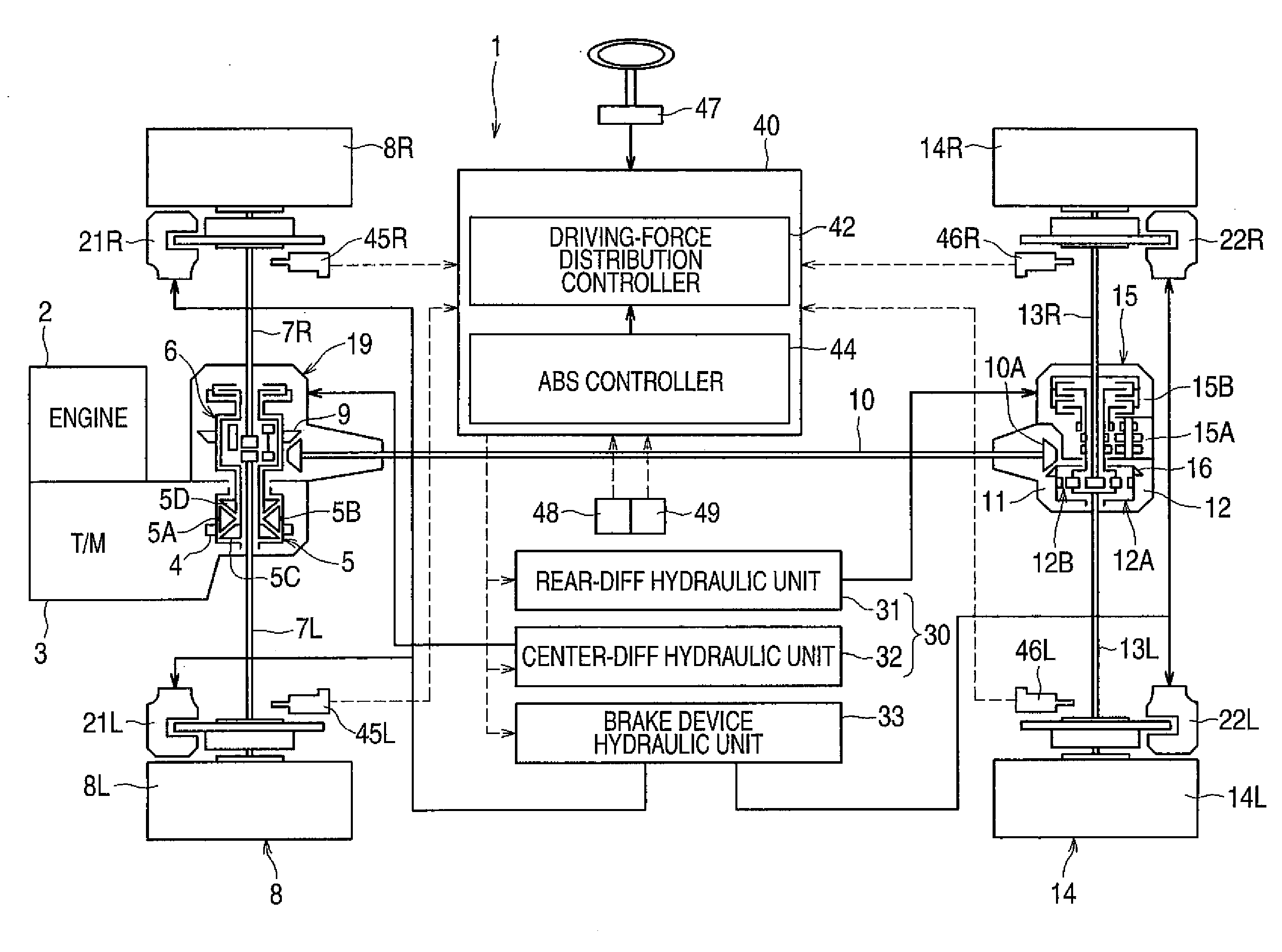
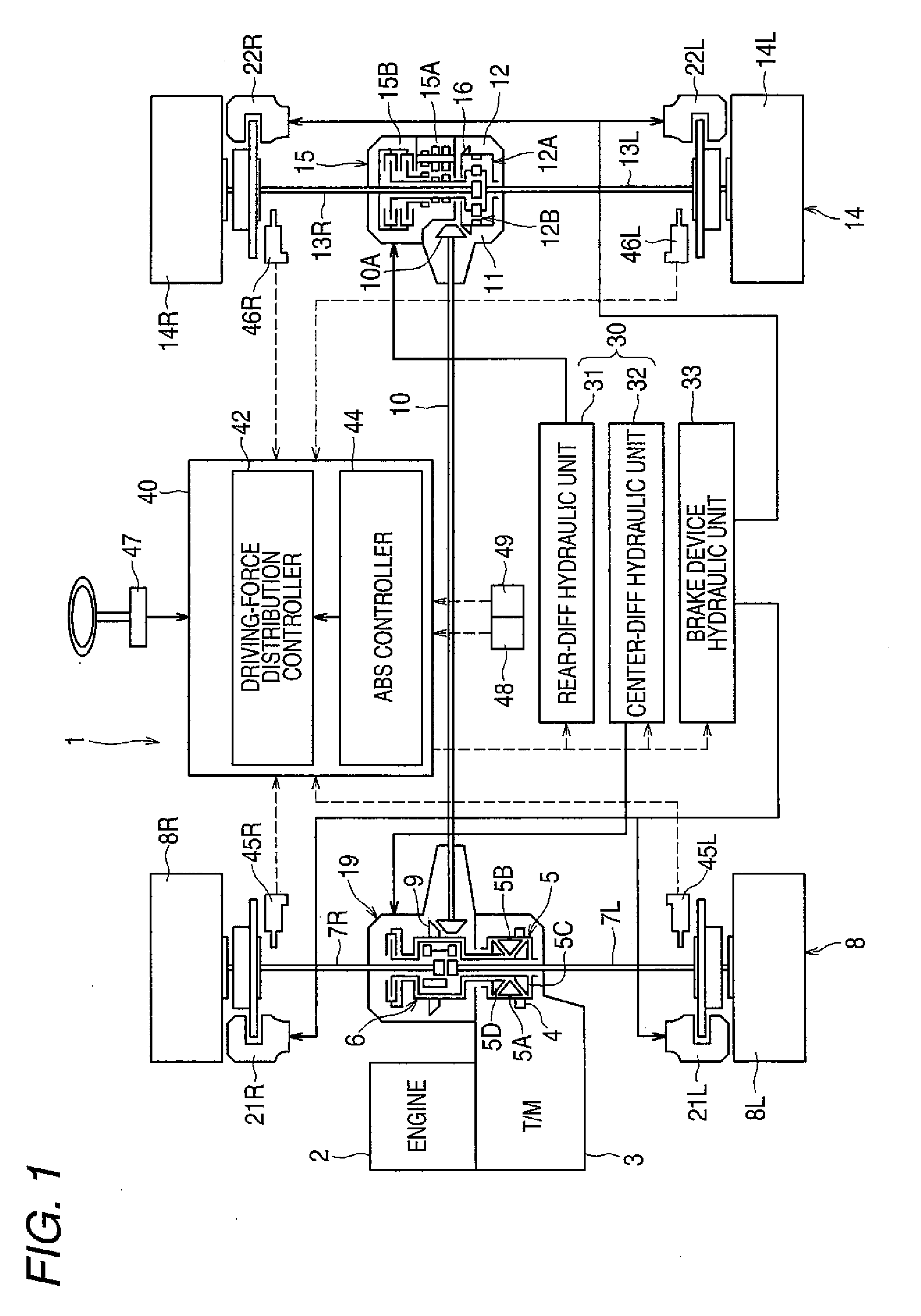
[0017]FIG. 1 is a schematic block diagram showing a constitution of the driving-force distribution control device according to the invention.

[0018]As shown in FIG. 1, a four-wheel drive vehicle 1, to which the driving-force distribution control device of the invention is applied, is provided with an engine 2, a transmission 3 and so on, so that the output of the engine 2 is transmitted through the transmission 3 and an intermediate gear mechanism 4 to a center differential (as will be called a center-diff) 5.

[0019]The output of the center-diff 5 is transmitted, on one hand, through a front differential (as will be called a front-diff) 6 from axles 7L and 7R to the left and right wheels 8L and 8R of front wheels 8 and, on the other hand, through a hypoid gear mechanism 9, a propeller shaft 10, a hypoid gear mechanism 11 on the rear wheel side ...


PUM


Abstract

A driving-force distribution control device includes a distributing mechanism, a distribution controller, an anti-skid brake system, an acceleration detector, a synthesized acceleration calculator and a control coefficient controller. The distributing mechanism is operable to variably distribute a driving force from an engine to individual drive wheels of a vehicle. The distribution controller is operable to control the distributing mechanism based on a running state of the vehicle. The acceleration detector is operable to detect a first acceleration in a front-rear direction and a second acceleration in a left-right direction of the vehicle. The synthesized acceleration calculator is operable to calculate a synthesized acceleration of the first acceleration and the second acceleration. The control coefficient controller is operable to indiscretely vary control coefficients for restricting the control of the distribution controller when the anti-skid brake system is activated, according to the calculated synthesized acceleration.

Description

BACKGROUND[0001]1. Field of the Invention[0002]The present invention relates to a driving-force distribution control device for distributing a driving force properly to the individual drive wheels of a vehicle.[0003]2. Description of the Related Art[0004]Drive wheels of an automobile is provided with a differential gear (a differential device) between the left wheels and the right wheels. As a result, the automobile can turn smoothly while allowing a difference in the rotating speed between the left-right wheels at the turning time. Generally in the case of a four-wheel drive car, moreover, not only the aforementioned left-right wheel differential gear but also a differential gear (a center-diff) is disposed between the front wheels and the rear wheels so that the rotating speed difference between the front and rear wheels can be allowed.[0005]In recent years, the cars of the kinds centering one imagining a rough road run or one imagining a sporty run are frequently provided with a ...

Claims


Application Information

Patent Timeline
IPC IPC(8): G06F19/00B60K17/348
CPCB60W10/119B60W10/184B60W30/045B60W2520/263B60W2520/105B60W2520/125B60W30/18172B60W30/02B60W10/12B60W10/18
Inventor USHIRODA, YUICHISAWASE, KAORUAONO, KAZUHIKOSAKATA, MAKOTOHAYASHIKAWA, KAZUFUMITAKAHASHI, NAOKISUZUKI, KEIJIMIURA, TAKAMI
Owner MITSUBISHI MOTORS CORP
Why Eureka
Try Eureka