Channel Anchoring Device For The Construction Industry

Inactive Publication Date: 2009-03-12
SEN YOU BAI
View PDF13 Cites 26 Cited by
  • Summary
  • Abstract
  • Description
  • Claims
  • Application Information

AI Technical Summary

Benefits of technology

[0006]Accordingly, to eliminate all of drawbacks mentioned in [0004] and [0005], the primary objective of the present invention is providing an improved channel anchoring device for the construct industry, which solves the problems that the prior art anchoring device cannot effectively prevent the shift of T-bolt along the channel, and the embedded steel part has larger in size and heavier in weight to cause inconvenience to reinforcement concrete installation.
[0012]Compared with the prior product of the channel anchoring device for the construction industry, the anchor channel of the present invention has smaller in size, lighter in weight, and prevents the shift of T-bolt along the channel, so as to cause less or even no interference to reinforcement concrete installation.
[0013]The said anchor channel of the present invention is made by the process of hot rolling. The continuously outspread serrations are designed to arrange on the inner surface of the return legs of the flanges of the anchor channel, which engage with the serrations arranged on the lower surface of the T-bolt head. Therefore, this can prevent the shift of T-bolt along the channel no matter in what orientation the device is placed.
[0014]The channel anchoring device of the present invention provides much higher shifting resistance than that of the known devices. As a result, the present invention can effectively solve the shifting of T-bolt due to the seismic loading under earthquake condition of greater than Richter scale rating 7.

Problems solved by technology

Since the inner surfaces of both the T-bolt head and the channel wall are smooth, such type of anchoring device cannot effectively prevent a shift of the T-bolt along the channel.
Moreover, the channel anchor shafts of above mentioned type are normally larger in size and may sometimes conflict with the reinforced concrete installation, in particular with the outermost layer of steel reinforcement bars.
Moreover, the steel re-bars required on the embedded steel part are also more in quantity and longer in length and thus causing much more interference to reinforced concrete installation.

Method used


Image

  • Channel Anchoring Device For The Construction Industry
  • Channel Anchoring Device For The Construction Industry
  • Channel Anchoring Device For The Construction Industry

Examples


Embodiment Construction

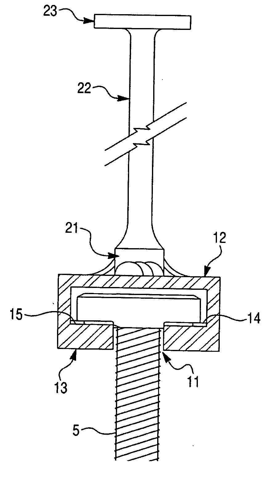
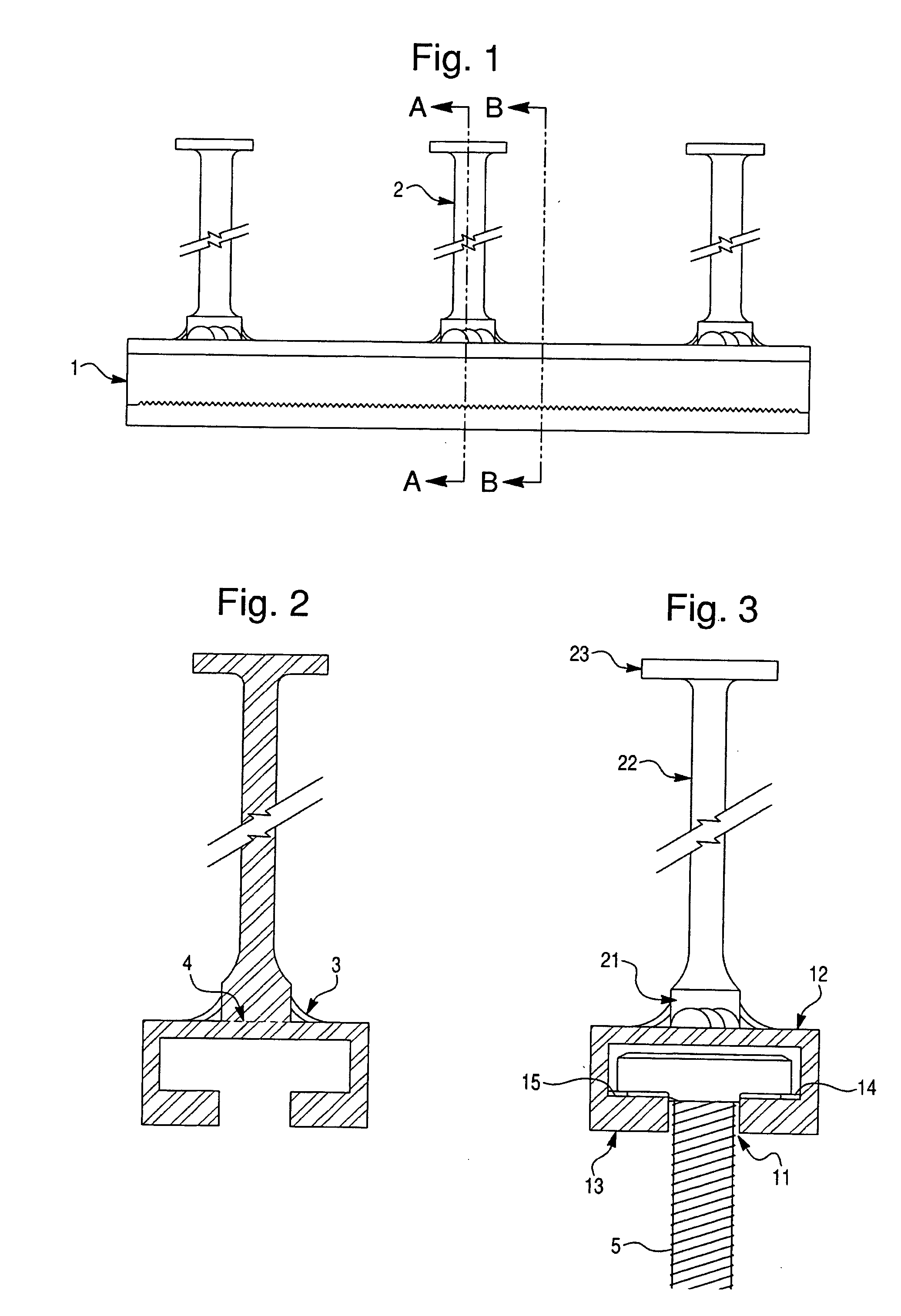
[0023]Referring now to FIG. 1 to FIG. 3, one embodiment of a channel anchoring device for construction industry in accordance with this invention is manufactured from hot rolled steel or stainless steel material, which is applicable to be cast into concrete structure. With the function as a coupling device, this channel anchoring device can attach with any construction elements and transfer the load from the attached element to the concrete.

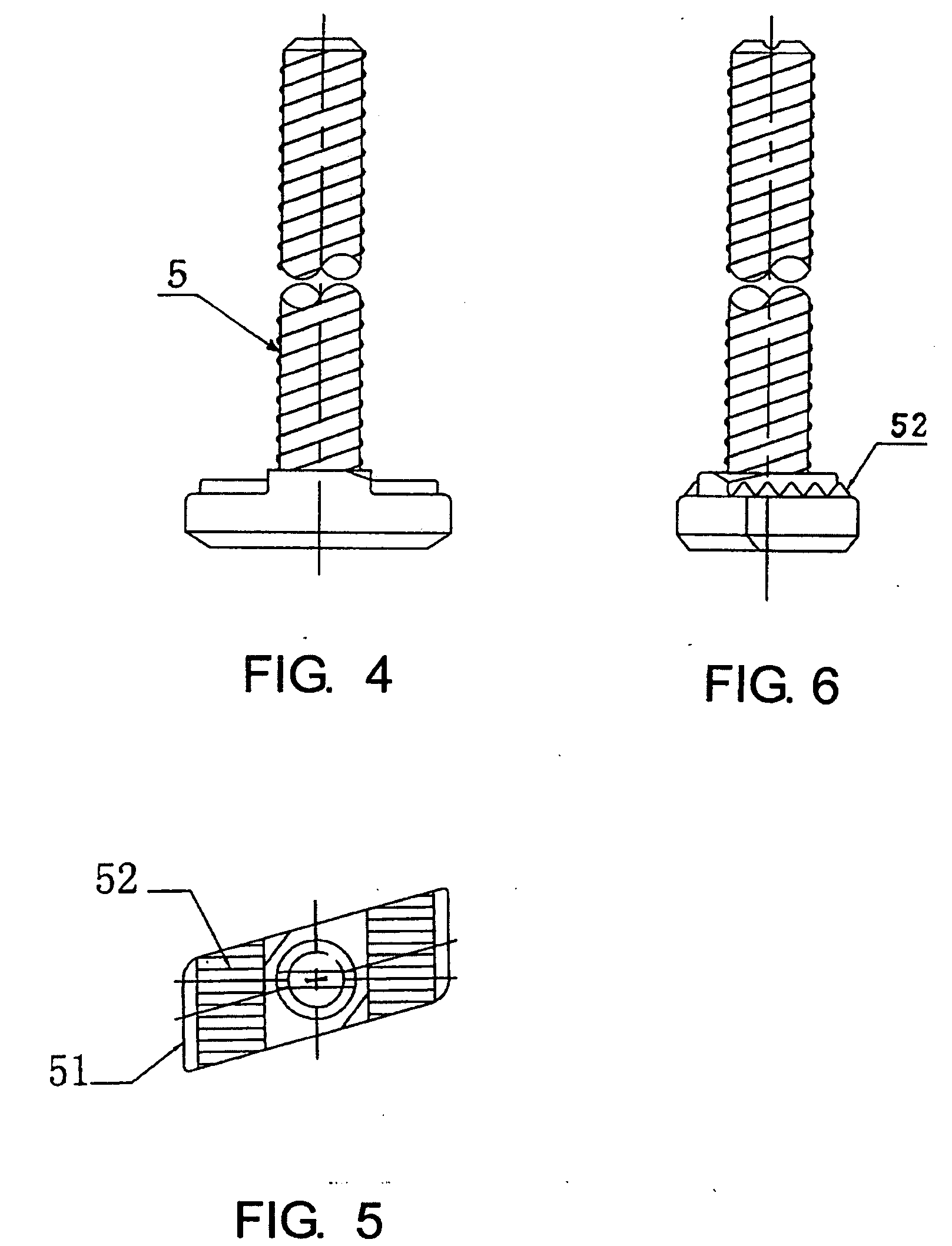
[0024]Referring now to FIG. 4 to FIG. 6, the channel anchoring device of this invention comprises an anchor channel 1 that is made from hot rolled C-shaped steel (or stainless steel) and a T-bolt 5, a plurality of ordinary steel (or stainless steel) anchor shafts 2 installed onto the anchor channel 1, which are cast into the concrete structure. The T-bolts 5 are inserted to install within the anchor channel 1.

[0025]The anchor channel 1 is a channel rail with a hollow interior, which is made from hot rolled steel or stainless steel material by the...


PUM


Abstract

The present invention relates to a channel anchoring device for construction industry, which comprises a channel rail with a hollow interior and T-type bolts, anchor shafts or steel base plates attached onto the exterior surface of the web of the channel, the channel anchoring device with anchor shafts is suitable to be embedded into the concrete structure, while the channel anchoring device with steel base plates is suitable to be welded onto the steel structure, the T-bolts are inserted into the gap between the return legs of two flanges of the channel. The said channel rail with a hollow interior is an anchoring channel, preferably manufactured from hot-rolled steel or stainless steel material by the process of hot rolling. The head of T-bolt is locked within the return legs of two flanges of the anchor channel. On the inner surface of the return legs of two flanges of the anchor channel, serrations are arranged respectively. On the lower surface of the head of T-bolt, serrations are also arranged; the serrations of T-bolt head connect with the serrations on the return legs of two flanges of the anchor channel in an engaged lock. The present invention prevents the shift of T-bolt along the channel, moreover no interference to reinforcement concrete installation.

Description

BACKGROUND OF THE INVENTION[0001]1. Field of the Invention[0002]The present invention relates to a channel anchoring device made of a metal, more particularly, to a channel anchoring device for the construction industry that is manufactured from the material, such as hot rolled steel (or stainless steel), which is suitable to be embedded into a concrete structure or to be attached to a steel structure, to secure other construction elements attached to the structure, and to make the load transferred from the construction elements to the structure.[0003]2. Prior Art[0004]Various channel anchoring devices of conventional type are known that are manufactured by the process of die casting, cold rolling, or hot rolling, which comprise a channel rail having a hollow interior and one or more anchor shafts attached thereto. The anchor shafts attached to the exterior surface of the web of the channel and embedded into the concrete. A T-shape bolt (hereinafter called T-bolt) can be inserted in...

Claims


Application Information

Patent Timeline
IPC IPC(8): E04B1/38
CPCF16B37/045E04B1/4107
Inventor SEN, YOU BAI
Owner SEN YOU BAI
Why Eureka
Try Eureka