Slack adjuster for railway vehicle brake rigging

a technology of slack adjuster and railway vehicle, which is applied in the direction of brake wear compensation mechanism, mechanical equipment, transportation and packaging, etc., can solve the problems of stopping the operation of the slack adjuster, affecting the relative longitudinal position of the train, etc., to prevent the condition of jamming, reduce frictional force, and retain the change in relative longitudinal position

Active Publication Date: 2009-03-12
WABTEC HLDG CORP
View PDF2 Cites 30 Cited by
  • Summary
  • Abstract
  • Description
  • Claims
  • Application Information

AI Technical Summary

Benefits of technology

[0005]This invention provides a double-acting compression actuable slack adjuster to adjust the slack in a railway vehicle brake rigging. The slack adjuster assembly includes an elongated hollow housing member restrained against rotation and pivotally connectable at a first end thereof to such brake rigging. An elongated rod member, restrained against rotation and pivotally connectable at a first end thereof to such brake rigging, is also provided and has at least a threaded portion adjacent a second end thereof. The threaded portion of the rod member extends into and is reciprocally movable within the housing through a second end of the housing. A positioning means movable between respective first abutting engagement, disengagement, and second abutting engagement positions is threadably engaged with the threaded portion of the rod member intermediate the ends thereof. The positioning means rotates about the threaded portion of the rod member when in the disengaged position thereby changing the length of the slack adjuster assembly by changing the relative longitudinal position between the housing and the rod member. A pair of opposite facing abutment surfaces positioned within a portion of the housing and a pair of opposed abutting surfaces carried by the positioning means for engaging respective adjacent abutment surfaces to resist rotation of the positioning means about the rod member when the positioning means is in one of the respective abutting engagement positions thereby retarding the change in relative longitudinal position between the housing and the rod member are provided. A first urging means is positioned between the positioning means and an abutment surface carried by the rod member for urging the positioning means into the disengaged position. A second urging means is positioned between the first end of the housing and the positioning means for overcoming a force applied by the first urging means and for urging the positioning means into the first abutting relationship position. A first overtravel control means is positioned to reciprocally move in a longitudinal direction adjacent the first end of the housing and is engageable with the second urging means for reducing the force applied by the second urging means to less than the force applied by the first urging means, thereby allowing the positioning means to move to the disengaged position. An overtravel control actuating means is positioned to engage the first overtravel control means for actuating the first overtravel control means in response to the travel distance of a brake force applying member connected to such brake rigging. A second overtravel control means is positioned in close proximity to the second end of the elongated hollow cylindrical housing member for reducing a frictional force generated during engagement of the respective abutment and abutting surfaces when the positioning means is in the second abutting engagement position and for preventing a jamming condition between the respective abutment and abutting surfaces when the elongated rod member is fully extended

Problems solved by technology

However, it has been found that when the slack adjuster is triggered and the elongated rod is allowed to fully extend due to improper adjustment during installation, the speed and inertia of the rotating cone lock nut is sufficient to exert greater than desirable force during contact with the abutment surface of the housing in the second abutting relationship position.
Such greater than desirable contact force causes jamming condition, due to friction and, more importantly, causes operation of the slack adjuster to cease.

Method used


Image

  • Slack adjuster for railway vehicle brake rigging
  • Slack adjuster for railway vehicle brake rigging
  • Slack adjuster for railway vehicle brake rigging

Examples


Embodiment Construction

[0018]Prior to proceeding to the more detailed description of the present invention, it should be noted that, for the sake of clarity and understanding, identical components which have identical functions have been identified with identical reference numerals throughout the several views illustrated in the drawing figures.

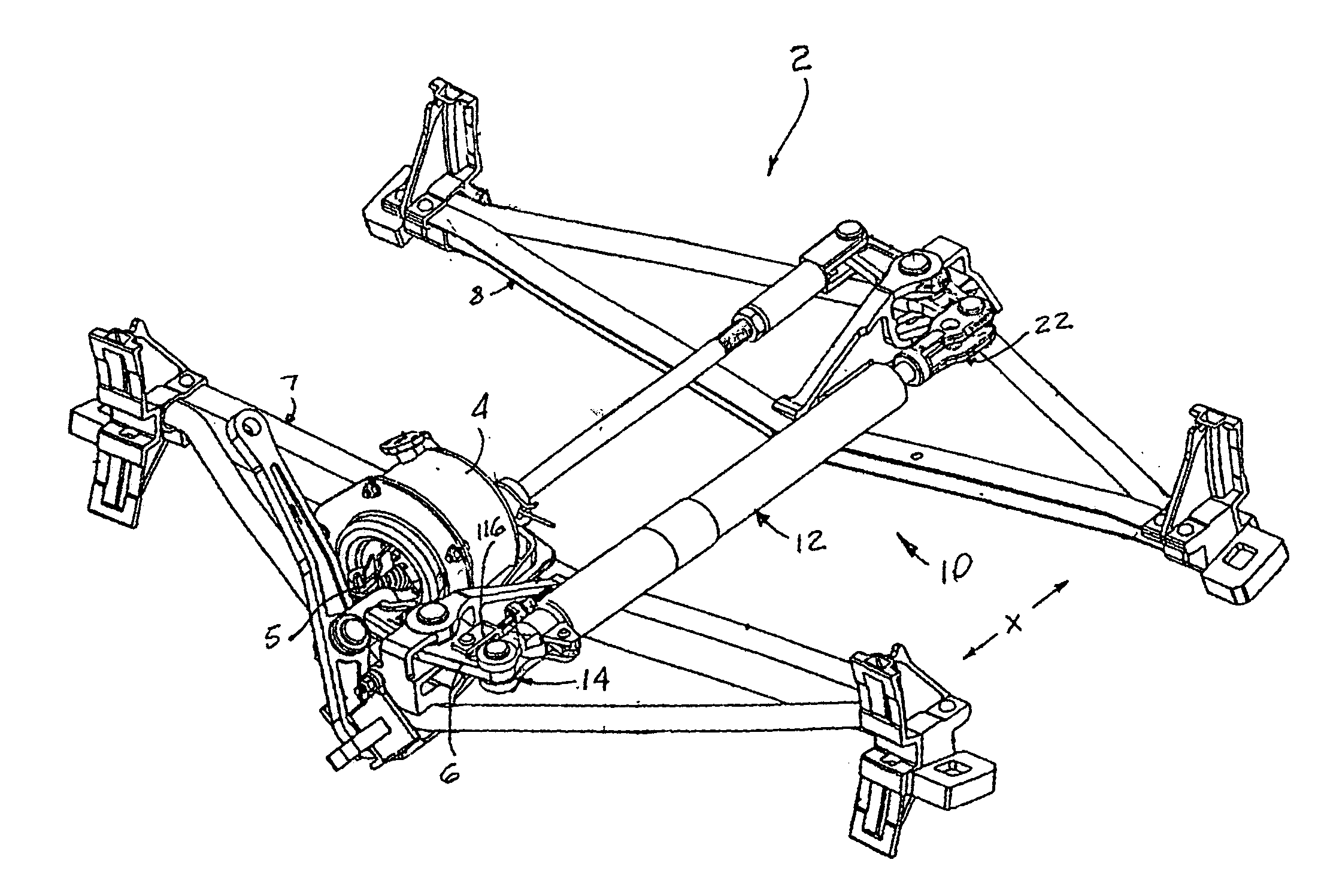
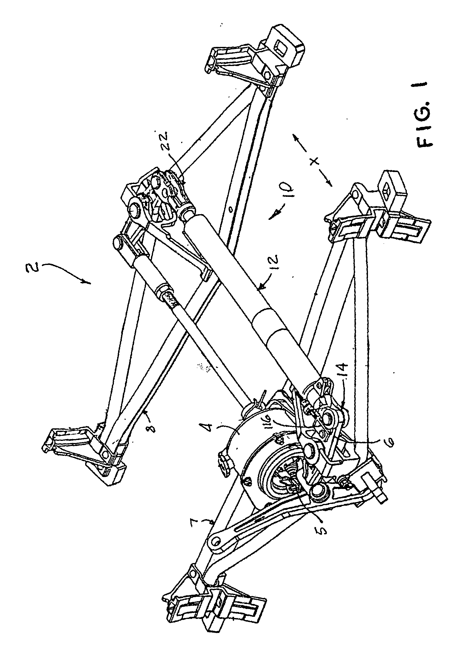
[0019]The structure and use of the present invention will be illustrated in combination with a double-acting compression actuatable slack adjuster assembly, generally designated as 10, which is taught in the U.S. Pat. No. 4,662,485 assigned to the assignee of the present invention. The disclosure of U.S. Pat. No. 4,662,485 is incorporated into this document by reference thereto. The double-acting compression actuatable slack adjuster assembly 10 is installed on a truck-mounted brake rigging, generally designated as 2, of a railway vehicle (not shown). The truck-mounted brake rigging illustrated in FIG. 1 is of a type as manufactured by the assignee of the present i...


PUM


Abstract

The present invention teaches a double-acting compression actuatable slack adjuster to adjust the slack in the brake rigging of a railway vehicle which includes a pair of elongated members movable with respect to each other in a longitudinal direction. A positioning device carrying a pair of opposed abutting surfaces is threadedly engaged with a threaded portion of the elongated rod. Pair of opposite facing abutment surfaces are positioned within the hollow housing. A first urging device is positioned to urge the positioning device into a disengaged position. A second urging device overcomes the force of the first urging device and urges an abutting surface on the positioning device into engagement with an adjacent abutment surface. A first overtravel control device is provided which is activated by a trigger device. A second overtravel control device is provided to prevent jamming condition of the positioning device with one of the abutment surfaces when the elongated rod is fully extended.

Description

CROSS-REFERENCE TO RELATED APPLICATIONS[0001]This application is closely related to U.S. Pat. No. 4,662,485 which is assigned to the assignee of the present invention. The disclosure of U.S. Pat. No. 4,662,485 is hereby incorporated by reference thereto.FIELD OF THE INVENTION[0002]The present invention relates, in general, to a double-acting compression actuable slack adjuster assembly which automatically adjusts the slack in the brake rigging of a railway vehicle and, more particularly, this invention relates to a double-acting compression actuable slack adjuster assembly which includes an overtravel control mechanism preventing irreversible lock-up of the slack adjuster being incorrectly installed and adjusted.BACKGROUND OF THE INVENTION[0003]As is generally well known, slack adjuster assemblies have been employed to automatically adjust the slack in the brake rigging of a railway vehicle. A particular slack adjuster of a double-acting compression type has been manufactured by the...

Claims


Application Information

Patent Timeline
Patent Type & Authority Applications(United States)
IPC IPC(8): F16D65/56
CPCB61H13/24F16D65/56B61H15/0028
Inventor SOMMERFELD, HOWARDBRANDT, STAFFAN
Owner WABTEC HLDG CORP
Why Eureka
Try Eureka