
Cleaning Apparatus and Manufacturing and Assembly Methods for the Same

a technology for cleaning equipment and manufacturing methods, applied in the field of cleaning equipment, can solve the problems of reducing the finish of the front portion, affecting the service life of the cleaning equipment, so as to facilitate repair, facilitate the change of color, and satisfy the variety of consumer tastes

Inactive Publication Date: 2009-03-12
LG ELECTRONICS INC
View PDF9 Cites 28 Cited by
  • Summary
  • Abstract
  • Description
  • Claims
  • Application Information

AI Technical Summary

Benefits of technology

[0021]An advantage of the cleaning apparatus and the manufacturing and assembly methods thereof according to the present invention is that it allows a consumer to conveniently change the color of the front portion of a washing machine, dryer, or other cleaning apparatus.
[0022]Another advantage of the cleaning apparatus and the manufacturing and assembly methods thereof according to the present invention is that it allows a variety of consumer tastes to be satisfied by changing only the front portion of the cleaning apparatus to different colors, patterns, or designs, without having to change the entire exterior.
[0023]A further advantage of the cleaning apparatus and the manufacturing and assembly methods thereof according to the present invention is that it allows replacement of only the section of the cleaning apparatus' outer perimeter that is damaged during transport or assembly without having to replace the entire outer portion, in order to facilitate repairs and reduce repair costs.
[0024]A still further object of the present invention is to provide a cleaning apparatus with a highly-finished edge portion for a high quality look and high value-added.

Problems solved by technology

Also, in washing machines or dryers according to the related art, the front panel is formed of a metal material, and is thus expensive to replace and puts a financial burden on the consumer.
Additionally, in cleaning apparatuses according to the related art, the control panel and the cabinet cover may be scratched, dented, or otherwise damaged during transport or use of the cleaning apparatus, so that the finish of the front portion is diminished.
Also, after a long period of use, a user may grow tired of the color of the front of the cleaning apparatus.

Method used


Image

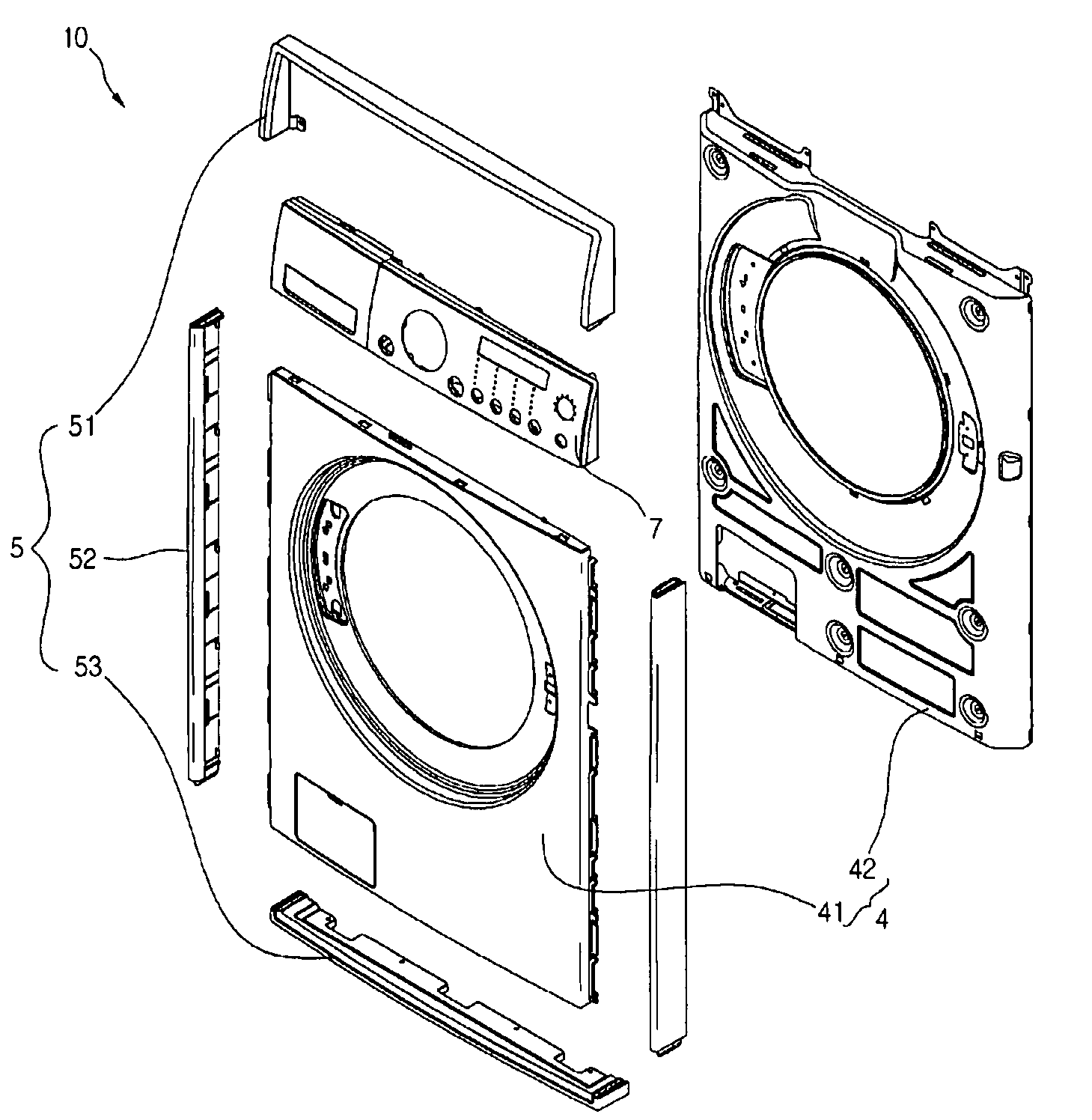
  • Cleaning Apparatus and Manufacturing and Assembly Methods for the Same
  • Cleaning Apparatus and Manufacturing and Assembly Methods for the Same
  • Cleaning Apparatus and Manufacturing and Assembly Methods for the Same

Examples


Embodiment Construction

[0050]Reference will now be made in detail to the preferred embodiments of the present invention, examples of which are illustrated in the accompanying drawings. Wherever possible, the same reference numbers will be used throughout the drawings to refer to the same or like parts.

[0051]To explain the cleaning apparatus according to the present invention, a drum washing machine will be used as a representative example. Here, the present invention covers not only drum washing machines, but also dryers for drying laundry, and even dishwashers.

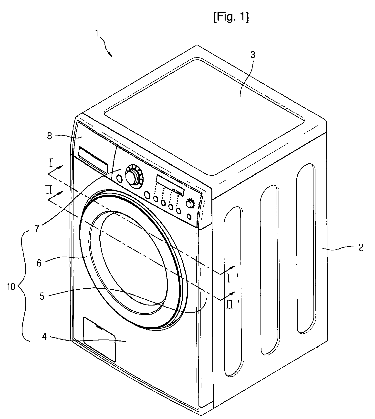
[0052]FIG. 1 is a perspective view of a cleaning apparatus according to the present invention.

[0053]In the first embodiment, a drum washing machine will be used as a representative example of cleaning apparatuses to which the present invention applies.

[0054]Referring to FIG. 1, a drum washing machine 1 having a front portion according to the present invention includes a cabinet 2 forming the exterior of the product with an opened front end, a top c...


PUM

PropertyMeasurementUnit
Temperatureaaaaaaaaaa

Abstract

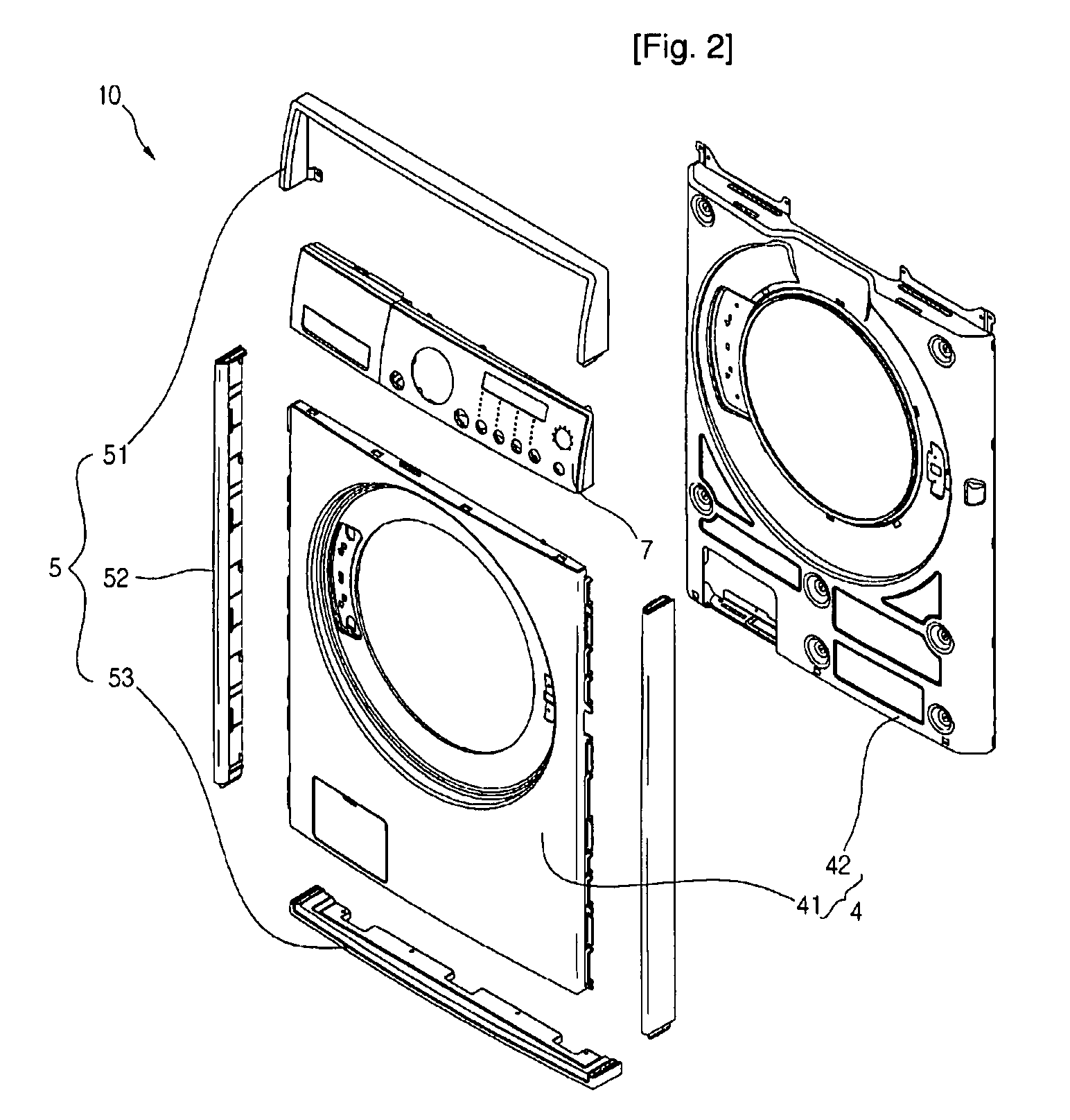
A cleaning apparatus is provided. The cleaning apparatus includes a cabinet (2), front panel (4), control panel (8), and fringe frame (5). The cabinet (2) is opened at a surface thereof. The front panel (4) is installed on a side of the cabinet (2), and includes a cabinet cover (42) forming a laundry inserting hole and anouter cover (41) coupled to a front surface of the cabinet cover (42) and color treated on its front surface through painting. The control panel (8) is mounted on top of the front panel (4). The fringe frame (5) covers the edge portion of the front panel (4) and the control panel (8).

Description

TECHNICAL FIELD[0001]The present invention relates to a cleaning apparatus, and more particularly, to an easily interchangeable structure for a front portion of a cleaning apparatus that enables the use of a variety of colors to decorate the front portion according to a user's preferences, and to manufacturing and assembly methods for the same.BACKGROUND ART[0002]Cleaning apparatuses generally include washing machines with a washing function for washing stains and dirt from laundry and dryers that have a drying function for drying wet laundry.[0003]In more detail, a washing machine has a cylindrical washing compartment, in which laundry in placed, after which the compartment is rotated to agitate the laundry in water with detergent dissolved in it, in order to remove impurities from the laundry. Washing machines can largely be divided into two categories: pulsator-type washing machines (with vertically-installed wash compartments and a pulsator installed at the bottom), and drum-typ...

Claims


Application Information

Patent Timeline
IPC IPC(8): D06F39/12B23P11/00
CPCD06F39/005D06F39/12Y10T29/49826A47L15/4293D06F39/14A47L15/4251D06F34/28
Inventor PARK, HYE-YONGKIM, BO YEONKWON, DAE HEEKIM, HYUN SEOKLEE, SEONG YEOLKIM, MYONG DEOK
Owner LG ELECTRONICS INC
Learn More