Organic electroluminescence element, and illuminating device and display device therewith

Active Publication Date: 2009-03-12
MERCK PATENT GMBH
View PDF5 Cites 193 Cited by
  • Summary
  • Abstract
  • Description
  • Claims
  • Application Information

AI Technical Summary

Benefits of technology

[0042]According to the present invention, in an organic electroluminescence element emitting white light, by the periodicity of a refractive index distribution having two-dimensional translational symmetry provided inside it, out of the light generated in a light-emitting layer and incident on interfaces at incidence angles equal to or more than the critical angle, light of three or more wavelengths in the visible light region is diffracted. This helps obtain increased luminance without degrading the quality of white light.
[0043]Moreover, according to the present invention, by use of the organic electroluminescence element structured as described above, it is possible to realize a high-luminance, long-life illuminating device. Moreover, by use of a liquid crystal panel

Problems solved by technology

This leads to disadvantages such as large device thickness and uneven brightness.
In Table 1, “Good” denotes a level inferior to “Excellent” or “Good” but still not unacceptable in practical terms.
As will be understood from Table 1, both fluorescence and phosphorescence in green are on the whole superior to those in other colors in terms of light emission efficiency and light emission lifetime; however, fluorescence in blue is inferior to that in green in terms of light emission lifetime, and so is fluorescence in red in terms of light emission efficiency and light emission lifetime; phosphorescence in blue has a far shorter lifetime tha

Method used


Image

  • Organic electroluminescence element, and illuminating device and display device therewith
  • Organic electroluminescence element, and illuminating device and display device therewith
  • Organic electroluminescence element, and illuminating device and display device therewith

Examples


first embodiment

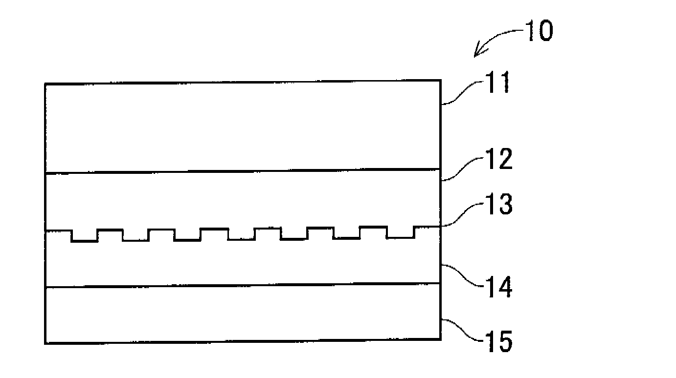
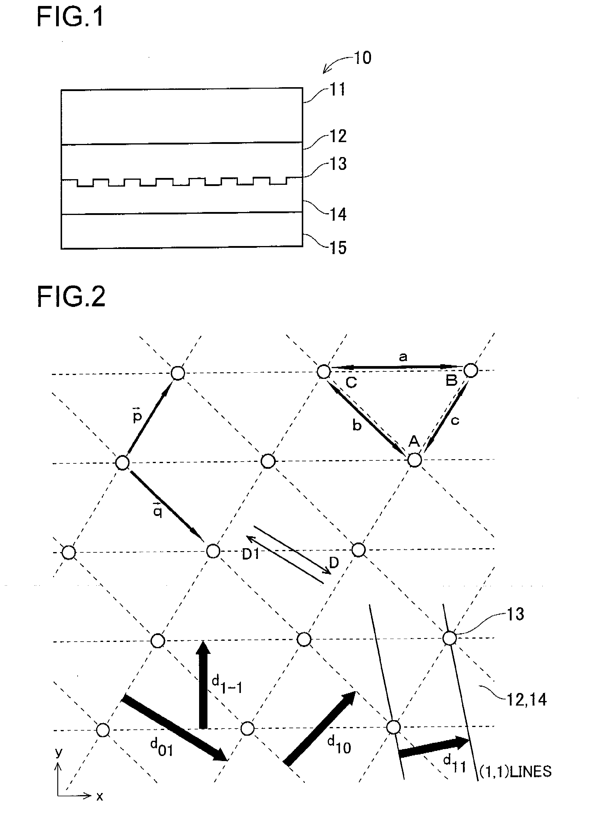
[0076]A first embodiment of the present invention will be described below with reference to the drawings. FIG. 1 is an outline structure diagram of an organic EL element according to the first embodiment, and FIG. 2 is an enlarged partial plan view of a diffraction grating.

[0077]First, the structure of the organic EL element 10 will be described. As shown in FIG. 1, the organic EL element 10 has a first electrode 12, a diffraction grating 13, a light-emitting layer 14, and a second electrode 15 provided in this order on a transparent substrate 11.

[0078]As the transparent substrate 11, any transparent material such as glass or resin may be used. There is no particular limitation on the kind, such as glass or plastic, of the material, examples of preferably used materials including glass, quartz, and transparent resin film. Particularly preferable is resin film that can make the organic EL element 10 flexible. The surface of the resin film may be coated with a film of an organic or in...

second embodiment

[0130]A second embodiment of the present invention will be described below with reference to the drawings. FIG. 5 is an enlarged partial plan view of a diffraction grating according to the second embodiment. The second embodiment is similar to the first embodiment in the structure of the organic EL element 10, but differs from it in that the diffraction grating has a square lattice. Accordingly, substantially the same parts between the two embodiments are identified by common reference signs.

[0131]In this embodiment, as shown in FIG. 5, the diffraction grating 13 has a square lattice. Here, when the grating constant of the square lattice is r, defining x- and y-axes and vectors p and q—the fundamental translational vectors—as shown in FIG. 5 gives

Vector p=(r,0)

Vector q=(0,r)

[0132]Accordingly, substituting (px, py)=(r, 0) and (qx, qy)=(0, r) in the formula representing the period dMN of the modulation structure on the diffraction grating 13 gives

dMN=r / √(M2+N2)

[0133]For example, assum...

third embodiment

[0143]A third embodiment of the present invention will be described below with reference to the drawings. FIG. 7 is an enlarged partial plan view of a diffraction grating according to the second embodiment. The third embodiment is similar to the first embodiment in the structure of the organic EL element 10, but differs from it in that the diffraction grating has a triangular lattice. Accordingly, substantially the same parts between the two embodiments are identified by common reference signs.

[0144]In this embodiment, as shown in FIG. 7, the diffraction grating 13 has a triangular lattice. Here, when the grating constant of the square lattice is r, defining x- and y-axes and vectors p and q—the fundamental translational vectors—as shown in FIG. 7 gives

Vector p=(r,0)

Vector q=(−r / 2,√3×r / 2)

[0145]Accordingly, substituting (px, py)=(r, 0) and (qx, qy)=(−r / 2, √3×r / 2) in the formula representing the period dMN of the modulation structure on the diffraction grating 13 gives

dMN=√3×r / {2×√(M2...


PUM


Abstract

In an organic EL element, at the interface between a first electrode and a light-emitting layer, a diffraction grating with grating constants a, b, and c is provided in the form of surface irregularities on the first electrode. The grating constants are determined such that, when the effective refractive index as light experiences in the organic EL element is n, with respect to the periods d01, d10, and d1−1 defining the periodicity of the diffraction grating, n×d01 corresponds to a red region and n×d10 and n×d1−1 correspond to a blue to green region.

Description

TECHNICAL FIELD[0001]The present invention relates to organic electroluminescence elements that emit white light, and to illuminating devices and display devices provided with such organic electroluminescence elements.BACKGROUND ART[0002]A kind of light-emitting element, organic electroluminescence elements (henceforth “organic EL elements”) can be made to emit light in desired colors by appropriate choice of light-emitting materials. By proper combination of light-emitting materials, it is possible even to obtain white light, and thus organic EL elements are expected to find uses as backlights, i.e. light-emitting devices, in liquid crystal display devices and, for their low power consumption combined with high luminance, as illuminating light sources to supplant fluorescent and tungsten lamps.[0003]When used as a backlight in a liquid crystal display device, an organic EL element is arranged on the back of a liquid crystal panel, and image display is achieved as a result of the li...

Claims


Application Information

Patent Timeline
IPC IPC(8): H01J1/63
CPCG02F1/133603G02F1/133606G02F2201/30H05B33/22H01L51/5275H05B33/14H01L51/5036H10K50/125H10K50/858
Inventor YOKOYAMA, MITSURU
Owner MERCK PATENT GMBH
Why Eureka
Try Eureka