Methods and systems for generating 3-dimensional computer images

a computer image and computer image technology, applied in the field of methods and systems for generating 3dimensional computer images, can solve the problems of increased storage requirements, scene may simply not be rendered, complex scene to be rendered, etc., and achieve the effect of improving memory usage and reducing wastag

Active Publication Date: 2009-03-12
IMAGINATION TECH LTD
View PDF10 Cites 49 Cited by
  • Summary
  • Abstract
  • Description
  • Claims
  • Application Information

AI Technical Summary

Benefits of technology

[0052]By using a look up table, which has contiguous portions allocated to each separate area, the actual memory pages where object data for that separate area is stored, do not need to be contiguous. This means that, object data, can span two memory pages, even though the memory pages

Problems solved by technology

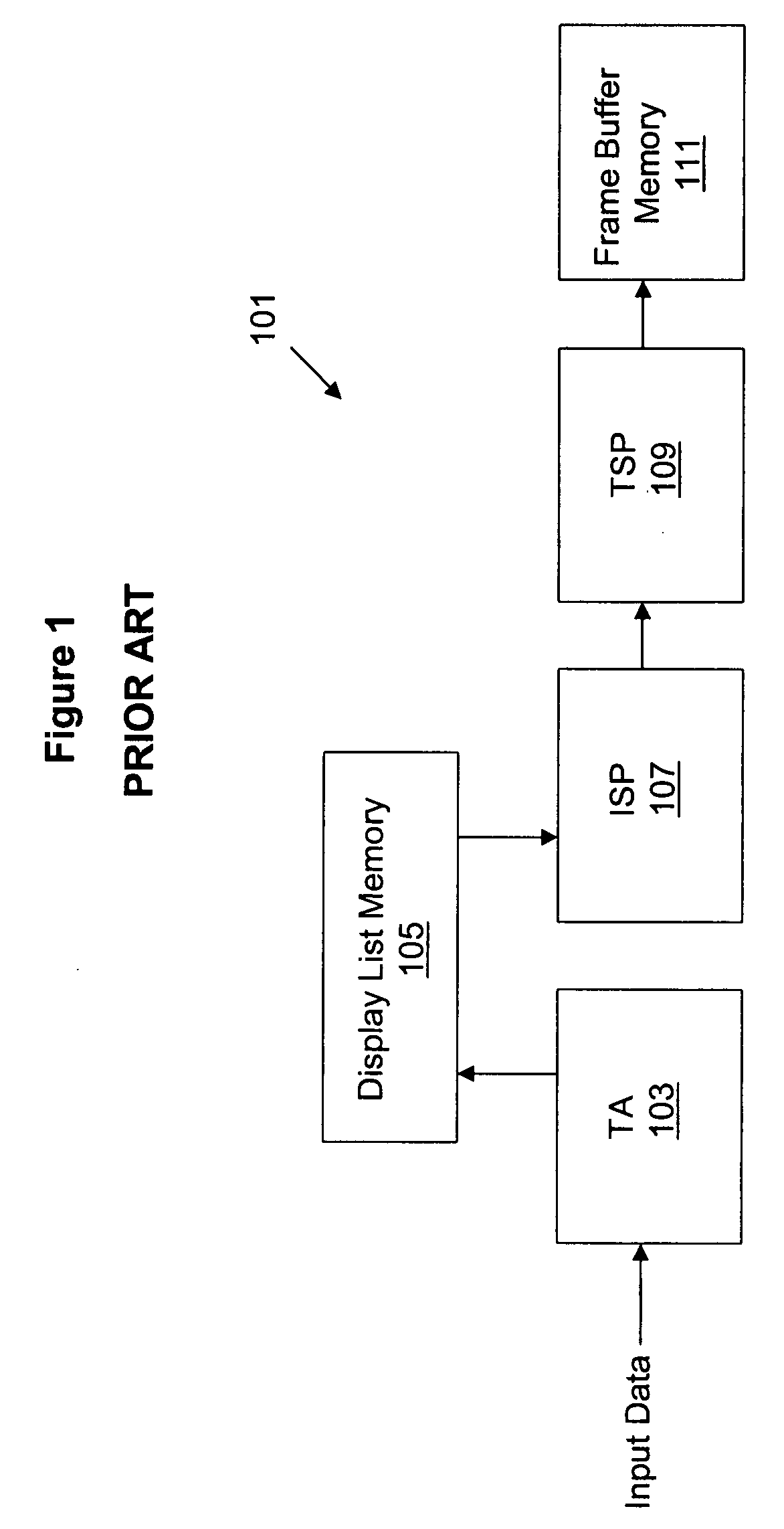
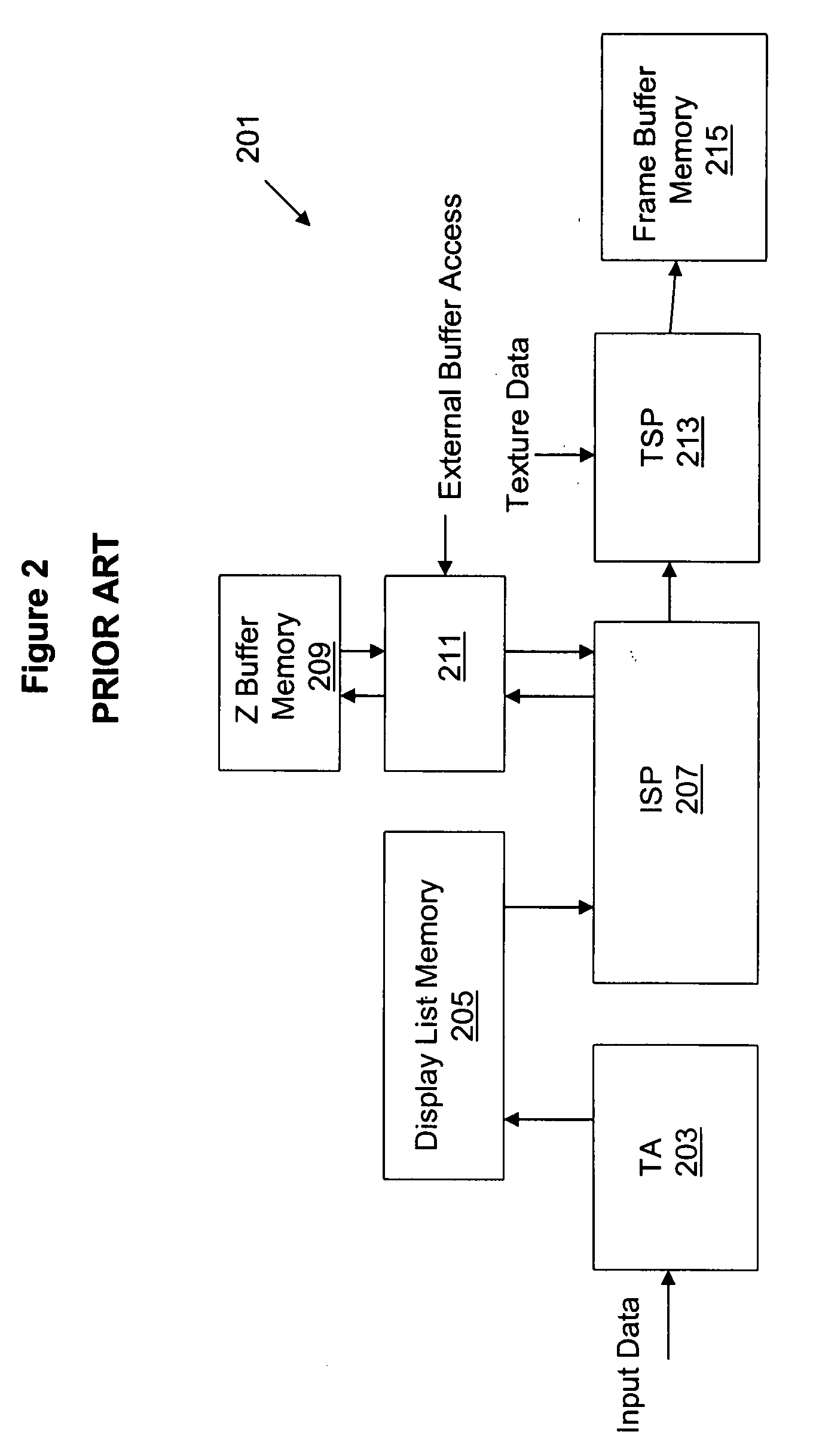
In the systems described above, a problem may arise as the complexity of the scene to be rendered increases.
Complex scenes require more 3-D object data for each tile to be stored in the display list memory and this means that storage requirements increase.
If the display list memory runs out of space, parts of the scene may simply not be rendered and this type of image corrupt

Method used


Image

  • Methods and systems for generating 3-dimensional computer images
  • Methods and systems for generating 3-dimensional computer images
  • Methods and systems for generating 3-dimensional computer images

Examples


first embodiment

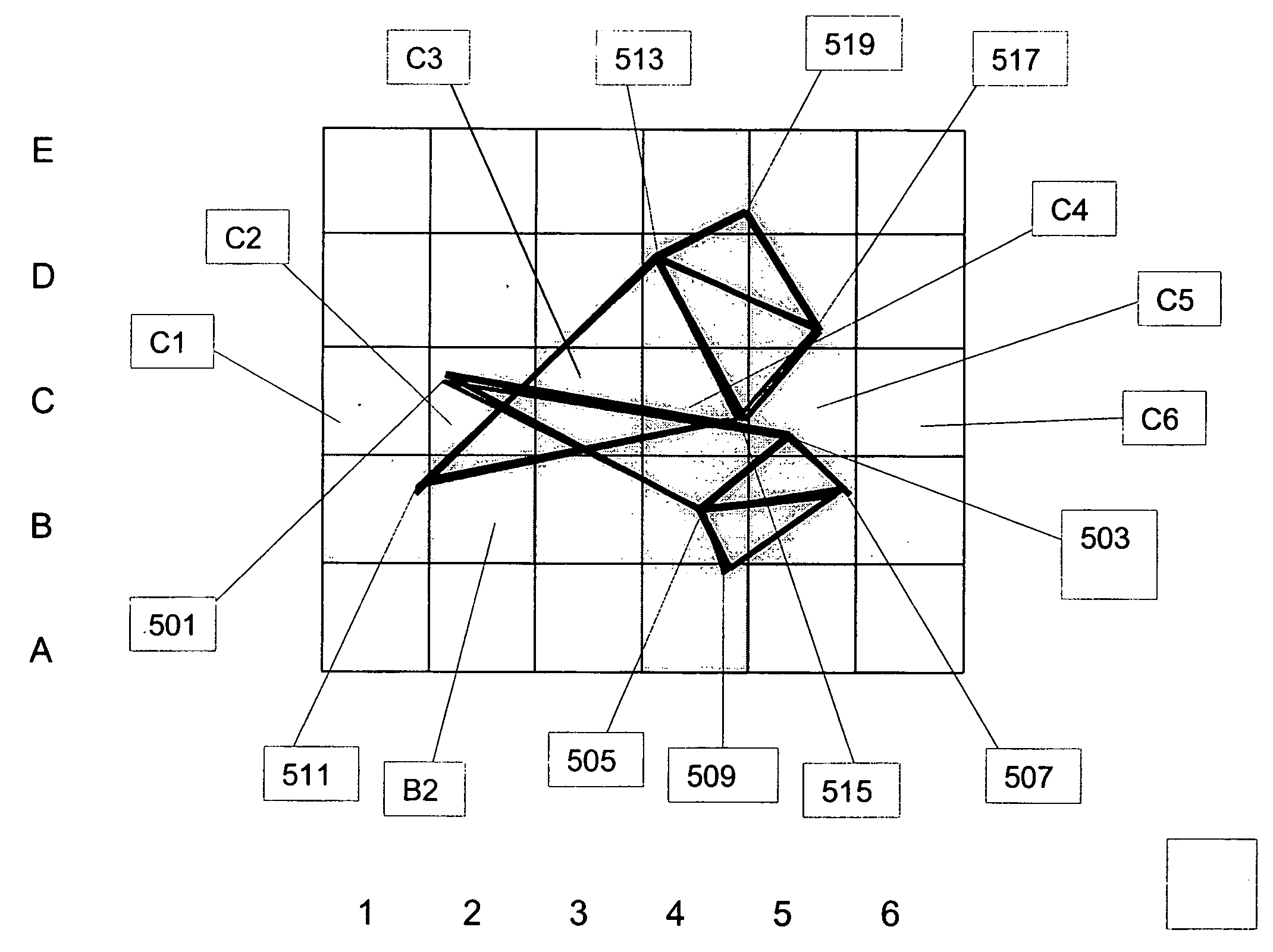
[0125]This arrangement of the third aspect of the invention provides two embodiments for solving this problem. The first embodiment proposed allows two memory pages to be allocated by the MTE for a primitive object. Thus, a particular primitive object can span two memory pages. So, when the primitive objects are written into the memory by the MTE, at the start, the memory manager allocates two pages of the memory to that macro-tile. (If it turns out that only one page is actually needed, the second page is simply used in the next write.) For all primitive objects, the number of vertices and primitives, together with the memory addresses of the primitive objects—vertex pointers—are sent to the TE to be added into the control stream of the tiles in which the primitive objects are visible. When the MTE is continuously writing primitive object data into the memory, it checks whether the memory write is going to span a page boundary. If the write will be contained within one memory page,...

second embodiment

[0129]The second embodiment proposed provides the Dynamic Parameter Management (DPM) with additional logic to guarantee that the pages are contiguous, and an additional small cache. If the pages are guaranteed to be contiguous, it is acceptable for the write for a given macro tile to span two pages.

[0130]In order to keep the pages allocated to each macro tile, when the MTE is writing, contiguous, the DPM maintains a look-up table page or pages, a portion being allocated for each macro tile. The pages allocated to the MTE are contiguous indexes in the look up table rather than contiguous memory page addresses. For each macro tile, there is a portion in the look-up table which provides pointers to the actual memory pages where the data is written. The portions in the look-up table are contiguous; this is achievable since they are allocated by the DPM at the start.

[0131]A counter is maintained in the DPM, for each macro tile (and the global list if being used) for page allocation to th...


PUM


Abstract

There are provided methods and apparatus for generating a 3-dimensional computer image. The image comprises a number of objects and is divided into separate areas. In a first aspect, control data to link to object data stored in a memory for each object is derived for two objects at a time. This improves processing and memory usage. In a second aspect, two or more separate areas can be processed in parallel by deriving control data for the two separate areas at a time. This improves processing time. To avoid fetching data for both areas, that is actually only applicable to one area, encoding is used in the control data. In a third aspect, object data can be stored on one or across two memory pages, and the control data includes one memory page address in the former case and two memory page addresses in the latter case. This improves memory usage. In a fourth aspect, object data can be stored across two non-contiguous memory pages, by using a look-up table with contiguous portions allocated for each object's object data. This also improves memory usage. In a fifth aspect, when partial rendering is used, and partial depth data is stored and subsequently updated, the depth data can be stored across two memory pages using link portions in the memory pages to either indicate the end of data storage or point to the next memory page. This also improves memory usage.

Description

FIELD OF THE INVENTION[0001]This invention relates to methods and apparatus for generating 3-dimensional computer images.BACKGROUND OF THE INVENTION[0002]In the applicant's UK Patent No. 2281682, there is described a 3-D rendering system for polygons in which each primitive object in the 3D scene is seen to be viewed as defined in a set of surfaces which are infinite. Each elementary area of the screen (e.g. pixel) in which an image is to be displayed has a ray projected through it from a viewpoint into the 3-D scene. The location of the intersection of the projected ray with each surface is then determined. From these intersections, it is then possible to determine whether any intersected surface is visible at that elementary area. The elementary area is then shaded for display in dependence on the results of the determination.[0003]The system can be implemented in a pipeline type processor comprising a number of cells, each of which can perform an intersection calculation with a s...

Claims


Application Information

Patent Timeline
IPC IPC(8): G06T15/30G06T15/00G06T15/06G06T15/40
CPCG06T15/005G06T15/40G06T15/06G06T15/405
Inventor REDSHAW, JONATHANYANG, XILE
Owner IMAGINATION TECH LTD
Why Eureka
Try Eureka