Multi-channel optical recording and/or reproducing apparatus and method of controlling the same

a multi-channel optical recording and/or reproducing technology, applied in the field of multi-channel optical recording and/or reproducing apparatus, can solve the problems of large dispersion of recording and reproducing performances using multi-channel pickup signals, light beams focused by an objective lens on a disc may have different wavefront aberrations, etc., to achieve the effect of increasing the tolerance of optical axis adjustment and reducing the difference in recording and/or reproducing performan

Inactive Publication Date: 2009-03-12
SAMSUNG ELECTRONICS CO LTD
View PDF5 Cites 2 Cited by
  • Summary
  • Abstract
  • Description
  • Claims
  • Application Information

AI Technical Summary

Benefits of technology

[0008]Aspects of the present invention provide a multi-channel optical recording and / or reproducing apparatus and a method of controlling the same, which reduces a difference in recording and / or reproducing performance between channels of a multi-channel optical pickup resulting from light spots having different wavefront aberrations and increases an optical axis adjustment tolerance by equalizing aberrations produced due to a displacement difference on an optical axis between light sources, a wavelength difference between the light sources, or a distance between the light sources.

Problems solved by technology

In these cases, however, the light beams focused by an objective lens on a disc may have differing wavefront aberrations due to a wavelength difference between the light beams emitted from the light sources, a displacement difference on an optical axis between the light sources, or a distance between the light sources.
The differences in the wavefront aberrations result in a great dispersion of recording and reproducing performances using the multi-channel pickup signals.

Method used


Image

  • Multi-channel optical recording and/or reproducing apparatus and method of controlling the same
  • Multi-channel optical recording and/or reproducing apparatus and method of controlling the same
  • Multi-channel optical recording and/or reproducing apparatus and method of controlling the same

Examples


Embodiment Construction

[0034]Reference will now be made in detail to the present embodiments of the present invention, examples of which are illustrated in the accompanying drawings, wherein like reference numerals refer to the like elements throughout. The embodiments are described below in order to explain the present invention by referring to the figures.

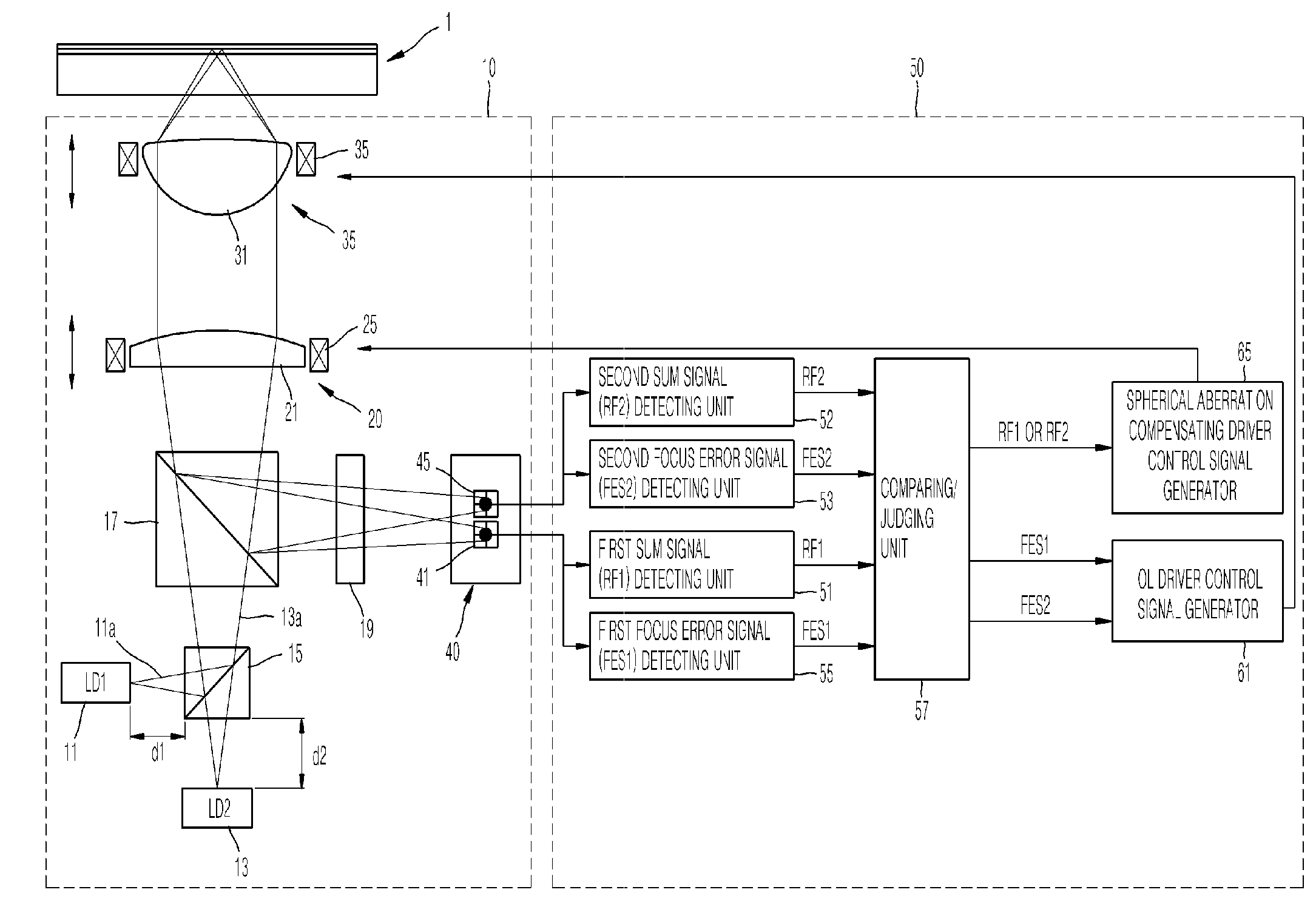
[0035]FIG. 1 is a graph illustrating defocus compared to jitter and defocus compared to a wavefront aberration as a defocus increases in an optical pickup system for a blu-ray disc (BD). Referring to FIG. 1, as a defocus increases, wavefront aberration increases linearly at the defocus increases from 0 to 400 nm. Jitter increases at a rate slower than the wavefront aberration as the defocus increases from 0 to 300 nm, but increases at a greater rate than the wavefront aberration when the amount of defocus increases from approximately 300 nm and greater. Accordingly, in the case of a multi-channel optical pickup using a plurality of light sources, the l...


PUM

PropertyMeasurementUnit
displacementaaaaaaaaaa
wavelengthaaaaaaaaaa
wavelength differenceaaaaaaaaaa

Abstract

A multi-channel optical recording and/or reproducing apparatus includes an optical pickup including a plurality of light sources, the optical pickup being adapted to emit a plurality of light beams to a corresponding plurality of tracks of an information storage medium and to detect a plurality of light beams reflected by the corresponding plurality of tracks of the information storage medium; and a control signal generating unit to generate a control signal which equalizes and controls aberrations occurring due to a wavelength difference between the plurality of light sources, a displacement difference on an optical axis between the light sources, or a distance between the light sources, based on detection signals generated according to the plurality of reflected light beams.

Description

CROSS-REFERENCE TO RELATED APPLICATION[0001]This application claims the benefit of Korean Application No. 2007-92818, filed Sep. 12, 2007 in the Korean Intellectual Property Office, the disclosure of which is incorporated herein by reference.BACKGROUND OF THE INVENTION[0002]1. Field of the Invention[0003]Aspects of the present invention relate to a multi-channel optical recording and / or reproducing apparatus, and more particularly, to a multi-channel optical recording and / or reproducing apparatus and a method of controlling the same, which simultaneously records signals in different tracks of an optical disc and / or simultaneously reproduces signals in different tracks of an optical disc using light beams emitted by a plurality of light sources to increase a data transfer rate (DTR).[0004]2. Description of the Related Art[0005]In optical data storage, the number of recording layers manufactured in blu-ray discs (BDs), HD-DVDs, DVDs, and other types of optical discs has been increased...

Claims


Application Information

Patent Timeline
Patent Type & Authority Applications(United States)
IPC IPC(8): G11B7/14G11B7/00G11B7/125G11B7/135
CPCG11B7/0909G11B7/127G11B7/1369G11B2007/0013G11B7/13927G11B7/14G11B7/1378
Inventor PARK, KYONGTAEKIM, TAE-KYUNGBAE, JAE-CHEOL
Owner SAMSUNG ELECTRONICS CO LTD
Why Eureka
Try Eureka