
Chemical injection using an adjustable depth air sparging system

Active Publication Date: 2009-03-12
USA REPRESENTED BY THE SEC OF THE NAVY
View PDF7 Cites 10 Cited by
  • Summary
  • Abstract
  • Description
  • Claims
  • Application Information

AI Technical Summary

Benefits of technology

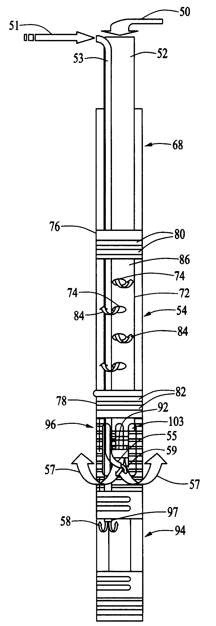
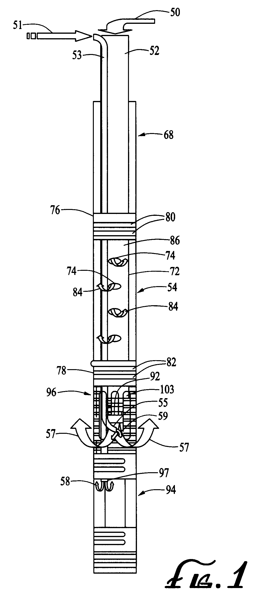
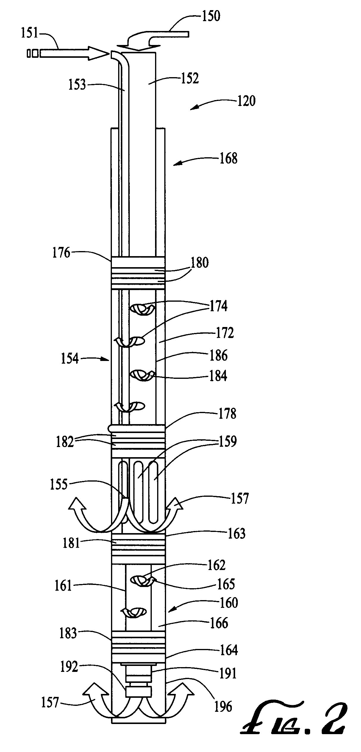
[0010]A fluid supply line connects the source of the chemical oxidizer or nutrient to a well head manifold. The well head manifold is pneumatically sealed using a compression fitting containing a rubber o-ring. The compression fitting prevents the source of air from escaping into the atmosphere through the well head. In addition, the compression fitting seal serves the purpose of mechanically locking the flow-through packer in place at a depth within the soil chosen by an operator. The pressurized air traveling through the flow-through packer inflates the packer, sealing the flow-through packer against the interior wall of a well casing and preventing injected air, chemical oxidizer or a nutrient from flowing back up the well casing. A pump supplies the chemical oxidizer or nutrient from a chemical storage tank to the well head manifold via a flexible hose type supply line. The chemical oxidizer or nutrient, which is under pressure, flows through a supply line located between an air supply tube and the interior wall of the well casing. The air supply tube which connects the blower and external air supply line to the flow-through packer, is located within the well casing. The pressurized air exits the upper portion of the well screen below the inflated flow-through packer. A fluid injector, located at the air injection point within the well screen, injects the chemical oxidizer or nutrient into the air stream. The air stream chemical oxidizer mixture or air stream nutrient mixture under pressure is then driven into the soil forming a chemical oxidizer plum and air channel matrix within the soil. The added chemical oxidizer or nutrient promotes the destruction of chlorinated aliphatic hydrocarbons in groundwater.

Problems solved by technology

The life-cycle costs to clean up these sites are uncertain, but are likely to exceed several billions of dollars nationally.
Although the chemistry of in-situ chemical oxidation is relatively simple, the technology is not a simple one to implement.
The soil's subsurface environment can be difficult to control, and it can be difficult to get adequate distribution of the oxidants within the soil's subsurface.
Current limitations to properly treat groundwater include the difficulty of bringing reactants into contact with contaminants, located in low permeability matrices in which diffusion and mass transfer are minimal.

Method used


Image

  • Chemical injection using an adjustable depth air sparging system
  • Chemical injection using an adjustable depth air sparging system
  • Chemical injection using an adjustable depth air sparging system

Examples


Embodiment Construction

[0015]Referring to FIGS. 1 and 3, FIG. 3 illustrates an adjustable depth air sparging system which provides for chemical injection, designated generally by the reference numeral 20, and which is used to remediate chlorinated solvents from groundwater within the soil 24. These chlorinated solvents are the most prevalent organic contaminants in groundwater and include chlorinated aliphatic hydrocarbons (CAHs), such as trichloroethylene and perchloroethylene. The adjustable depth air sparging system 20 injects air under pressure mixed with a chemical oxidizer or a nutrient into the soil 24 to remediate the soil neutralizing the environmentally harmful contaminants including the CAHs.

[0016]As shown FIG. 3, the adjustable depth air sparging system 20 which includes chemical injection is vertically positioned within the soil 24 and passes through the vadoze zone 22 of the soil 24 into the saturated zone 26 of the soil 24. It should be noted that the saturated zone 26 of the soil 24 is hom...


PUM

PropertyMeasurementUnit
Pressureaaaaaaaaaa
Depthaaaaaaaaaa

Abstract

A supplemental fluid adjustable depth air sparging system which is used to remediate contaminants from groundwater within the soil. An adjustable depth air injection point injects compressed air mixed with a chemical oxidizer or nutrient into saturated or groundwater regions of the soil's subsurface to remove contaminants including chlorinated solvents from the soil's subsurface.

Description

BACKGROUND OF THE INVENTION[0001]1. Field of the Invention[0002]The present invention relates generally to a system for removing environmentally harmful contaminants from saturated or ground water regions of the soil subsurface. More specifically, the present invention relates to a system which provides supplemental fluids which are either chemical oxidizers or nutrients which promote accelerated bioremediation of targeted contaminants within the subsurface of the soil and groundwater.[0003]2. Description of the Prior Art[0004]The U.S. Government's Department of Defense estimates that 6,045 of their groundwater sites are either under investigation for environmentally harmful contaminants or identified for future cleanup and restoration. Chlorinated solvents are the most prevalent organic contaminants in groundwater. Chlorinated aliphatic hydrocarbons (CAHs), such as trichloroethylene and perchloroethylene, have been found at approximately 80% of all Superfund sites having groundwate...

Claims


Application Information

Patent Timeline
IPC IPC(8): A62D3/00
CPCB09C1/00B09C1/10B09C1/08B09C1/002
Inventor DRUCKER, ANDREW SCOTT
Owner USA REPRESENTED BY THE SEC OF THE NAVY
Learn More