Control for an internal-combustion engine

a technology of combustion engine and control panel, which is applied in the direction of electrical control, process and machine control, etc., can solve the problems of increasing the number of parameters and computation load, the increase of the computation load of controlling variables, and the control may decrease the exhaust gas pressure, so as to achieve fewer settings, the effect of reducing the amount of fuel injection and increasing the accuracy of fuel injection

Inactive Publication Date: 2009-03-12
HONDA MOTOR CO LTD
View PDF13 Cites 13 Cited by
  • Summary
  • Abstract
  • Description
  • Claims
  • Application Information

AI Technical Summary

Benefits of technology

[0008]According to one embodiment of the invention, a fuel injection amount is determined based on the intake air amount thus calculated. Because the intake air

Problems solved by technology

Especially, if a control that uses the absolute pressure of the intake manifold is performed at high altitude, such a control may decrease an exhaust gas pressure, internal EGR amount, and the like.
Further, computation load for calculating cont

Method used


Image

  • Control for an internal-combustion engine
  • Control for an internal-combustion engine
  • Control for an internal-combustion engine

Examples


Embodiment Construction

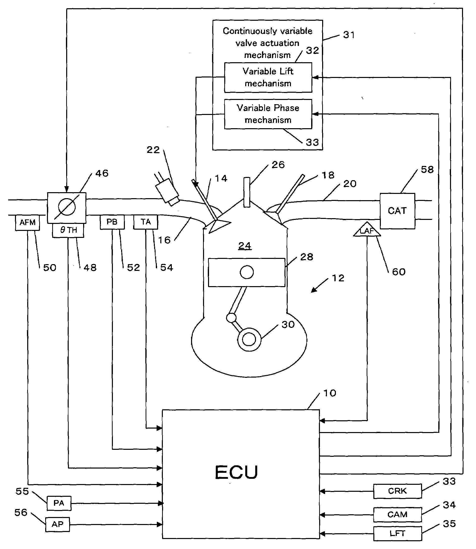
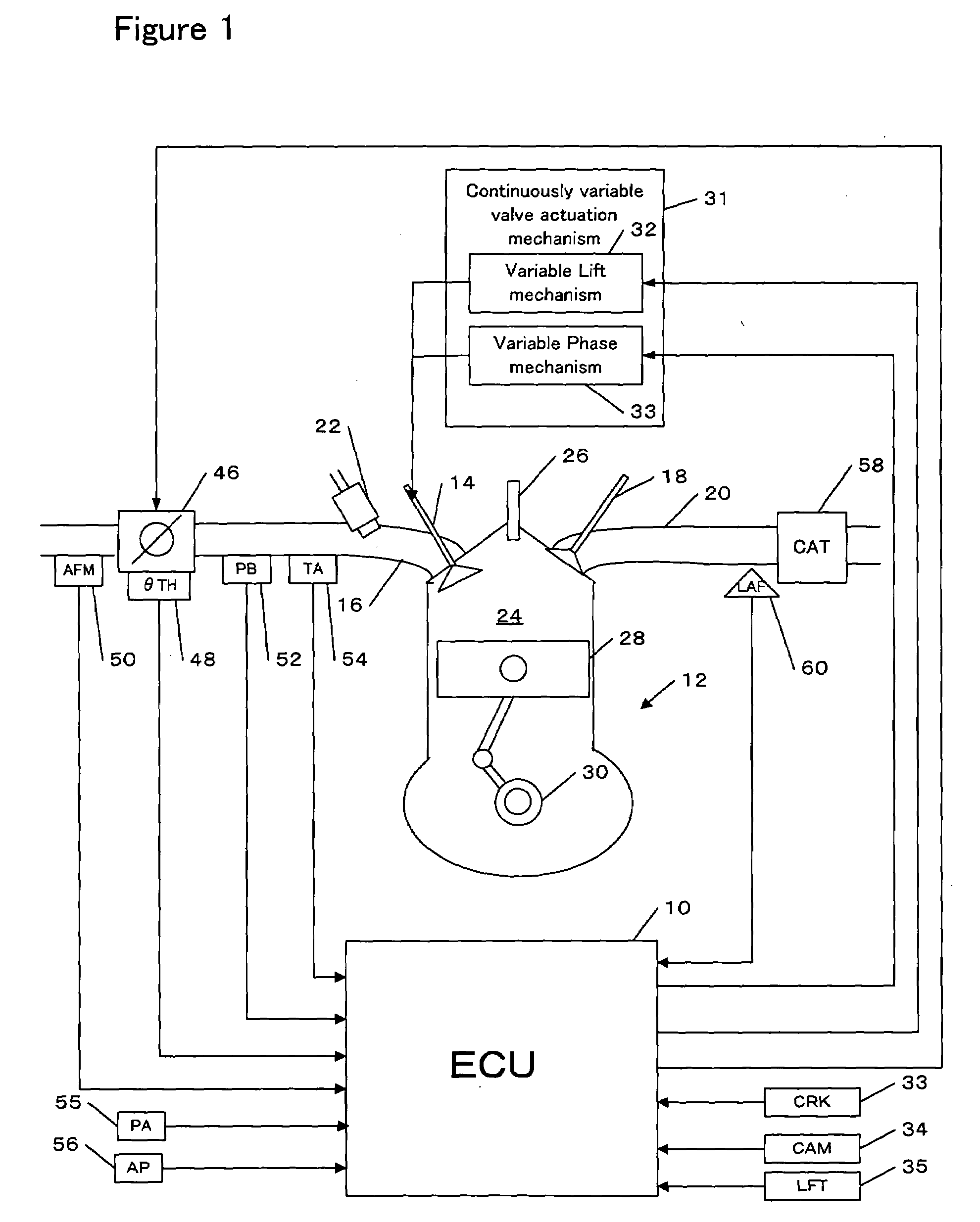
[0023]Preferred embodiments of the present invention will be described referring to the attached drawings. FIG. 1 is an overall system structure of an engine and its control unit in accordance with one embodiment of the present invention.

[0024]An electronic control unit (hereinafter referred to as an “ECU”) 10 is a computer having an input / output interface, a central processing unit (CPU) and a memory. One or more programs for implementing various controls for the vehicle and data required for executing the programs may be stored in the memory. One or more programs for controls according to the invention, data and one or more maps used for executing the programs may be also stored in the memory. The ECU 10 receives data sent from each part of the vehicle via the input / output interface, carries out operations to generate control signals, and sends out the control signals for controlling each part of the vehicle.

[0025]An engine 12 is, for example, a 4-cycle engine equipped with four c...


PUM


Abstract

A control for an engine having a variable valve actuation mechanism is provided. A map indicating a correlation among a rotational speed, a gauge pressure of an intake manifold, a lift amount of an intake valve, a phase of the intake valve and an intake air amount of the engine under a reference condition of a predetermined reference atmospheric pressure and a predetermined reference intake air temperature is defined. An intake air amount for the reference condition is determined as a reference intake air amount by referring to the map based on a current rotational speed, a current gauge pressure, a current lift amount and a current phase. The reference intake air amount is corrected with a ratio between an air density under a current condition of a current atmospheric pressure, a current intake air temperature and a current gauge pressure and an air density under the reference condition to calculate an intake air amount for the current condition.

Description

BACKGROUND OF THE INVENTION[0001]The present invention relates to a control for an internal-combustion engine (which will be hereinafter referred to as an “engine”).[0002]In recent engines, as described in Japanese Patent Application Publication No. 2005-120990, mounting, on an engine, a mechanism that is capable of changing a lift amount and a phase of an intake valve and controlling the amount of intake air into the engine through the mechanism are proposed[0003]On the other hand, as described in Japanese Patent Application Publication No. H10-073068, an absolute pressure of an intake manifold is generally used for controlling an engine.[0004]The atmospheric pressure at high altitude is lower than the atmospheric pressure at low altitude. Such a lower atmospheric pressure may influence various controls for an engine. Especially, if a control that uses the absolute pressure of the intake manifold is performed at high altitude, such a control may decrease an exhaust gas pressure, in...

Claims


Application Information

Patent Timeline
IPC IPC(8): F02D41/00
CPCF02D13/0226F02D41/0002F02D41/04F02D41/182F02D2041/001F02D2200/0402Y02T10/18F02D2200/0414F02D2200/703F02P5/1514Y02T10/46Y02T10/42F02D2200/0406Y02T10/12Y02T10/40
Inventor TAKAMIYA, HIDEHARUIRIE, SEIICHIROKOUDA, YUTAKAKOMORIYA, ISAO
Owner HONDA MOTOR CO LTD
Why Eureka
Try Eureka