Electronic valve system

Inactive Publication Date: 2009-03-19
DENSO CORP
View PDF7 Cites 2 Cited by
  • Summary
  • Abstract
  • Description
  • Claims
  • Application Information

AI Technical Summary

Benefits of technology

[0009]Holding the ignition signal in the first state prevents ignition occurring in the cylinder, which in turn could cause ignition of fuel in the intake manifold. Holding the signal in the first state for a number of cycles of the engine a

Problems solved by technology

Holding the ignition signal in the first state prevents ignition occurring in t

Method used


Image

  • Electronic valve system
  • Electronic valve system
  • Electronic valve system

Examples


Example

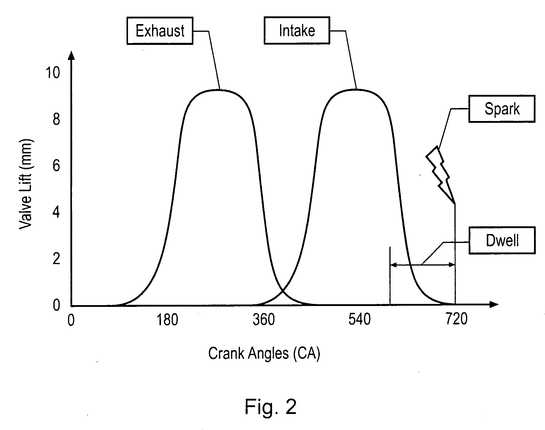
[0021]An embodiment of the invention can prevent unwanted ignition of fuel in an internal combustion engine cylinder in the event of a fault in an electronically activated intake valve following opening of the valve. In an embodiment of the invention, in response to detection of an intake valve fault in respect of a cylinder, the ignition signal for the cylinder is held in the first state for a number of cycles of the internal combustion engine to permit fuel in the cylinder to dissipate.

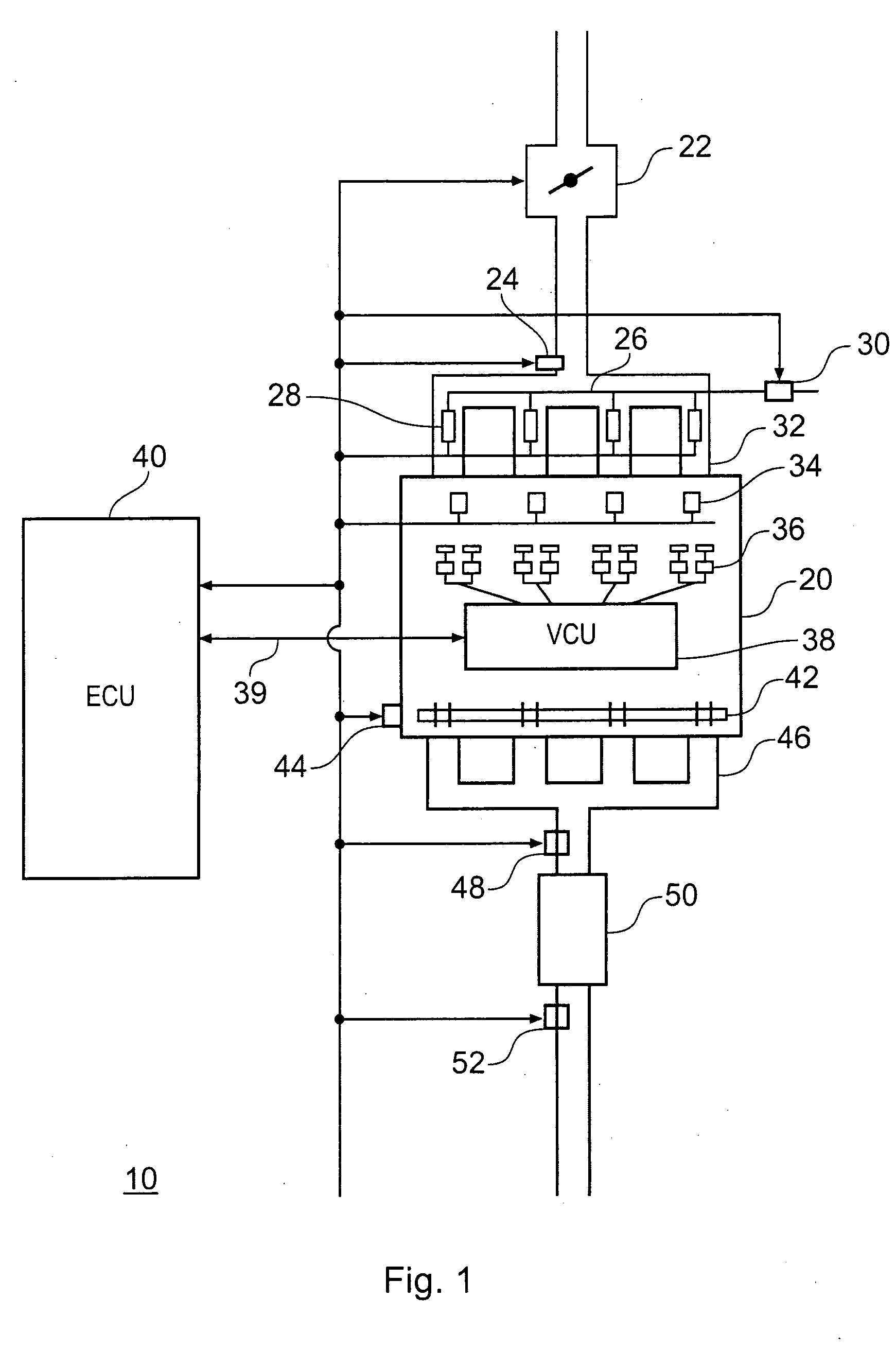
[0022]FIG. 1 provides a schematic overview of an electronic valve actuation (EVA) engine system 10. The internal combustion engine 20 represented in FIG. 1 is a four cylinder gasoline engine. The engine system is controlled by an engine control unit 40 which is connected to various sensors and control subsystems of the engine system 10. The ECU controls the operation of a throttle 22 at the intake side of the engine. A manifold pressure sensor 24 in an intake manifold 32 provides control signals to ...


PUM


Abstract

An internal combustion engine comprises a number of cylinders. The cylinders have electronically activated intake valves. Ignition coils for the cylinders are responsive to respective ignition signals such that charge accumulates in a coil for a cylinder when the ignition signal for the cylinder has a first state and then the charge causes ignition for the cylinder when the ignition signal for the cylinder changes to a second state. In response to detecting an intake valve fault in respect of a cylinder, the ignition signal for the cylinder is held in the first state for a number of cycles of the internal combustion engine, and is then switched to a second state to safely discharge the primary coil without combustion in the cylinder.

Description

BACKGROUND[0001]1. Field[0002]Non-limiting example embodiments of the present invention relate to the electronic valve systems for an internal combustion engine.[0003]2. Related Art[0004]Conventionally, internal combustion engine valve operation has been controlled using camshafts mechanically linked to the rotation of the engine crankshaft. With the continued aim of engine and vehicle manufacturers to improve engines by way of reducing emissions and fuel consumption, and to increase performance for better driveability, various techniques to improve valve control have been employed, such as, variable valve timing.[0005]In order, further, to provide better control of valve actuation, it is proposed to employ electronic valve actuation systems. Electronic valve actuation is also sometimes known as electromagnetic valve actuation, electromechanical valve actuation, electrical valve actuation and the like. For consistency, the term electronic valve actuation will be used herein. An elec...

Claims


Application Information

Patent Timeline
IPC IPC(8): F01L9/04F01L9/20
CPCF01L9/04F01L2800/12F02D41/221F02D41/266F02D2041/001Y02T10/40F02P3/0554F02P17/02F02P17/12F02P2017/123F02P3/0456F01L9/20
Inventor YOUNG, BARRY
Owner DENSO CORP
Why Eureka
Try Eureka