Helicopter with an auxiliary lubricating circuit

Active Publication Date: 2009-03-19
LEONARDO FINMECCANICA SPA
View PDF2 Cites 25 Cited by
  • Summary
  • Abstract
  • Description
  • Claims
  • Application Information

AI Technical Summary

Benefits of technology

[0007]It is an object of the present invention to provide a helicopter designed

Problems solved by technology

In the event of damage to the lubricating circuit, the oil p

Method used


Image

  • Helicopter with an auxiliary lubricating circuit
  • Helicopter with an auxiliary lubricating circuit
  • Helicopter with an auxiliary lubricating circuit

Examples


Embodiment Construction

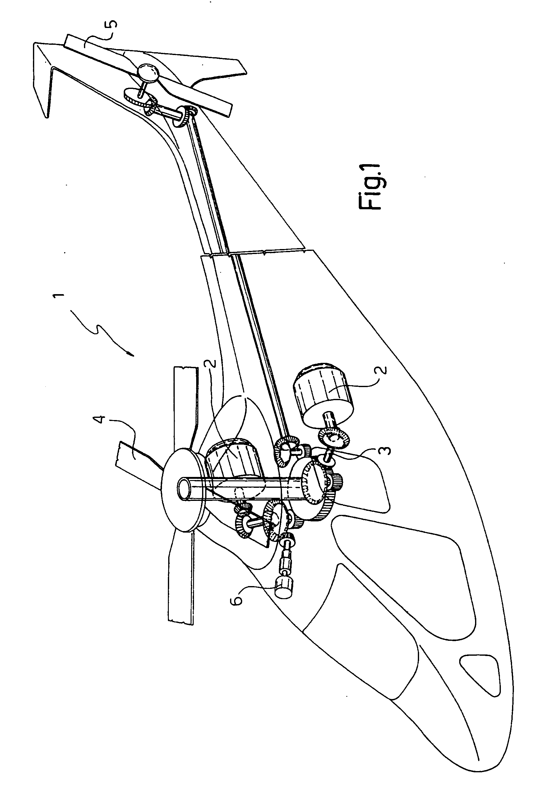
[0012]Number 1 in FIG. 1 indicates a helicopter comprising two turbines 2; a main rotor 4; a tail rotor 5; and a primary transmission 3 for transmitting motion from turbines 2 to main rotor 4 and tail rotor 5.

[0013]Helicopter 1 also comprises a number of secondary transmissions 6 (shown schematically) for transmitting motion from primary transmission 3 to respective known accessory devices (not shown), i.e. for powering respective on-board equipment, for example.

[0014]As described in more detail below, each transmission 3, 6 must be oil-lubricated for it to function properly.

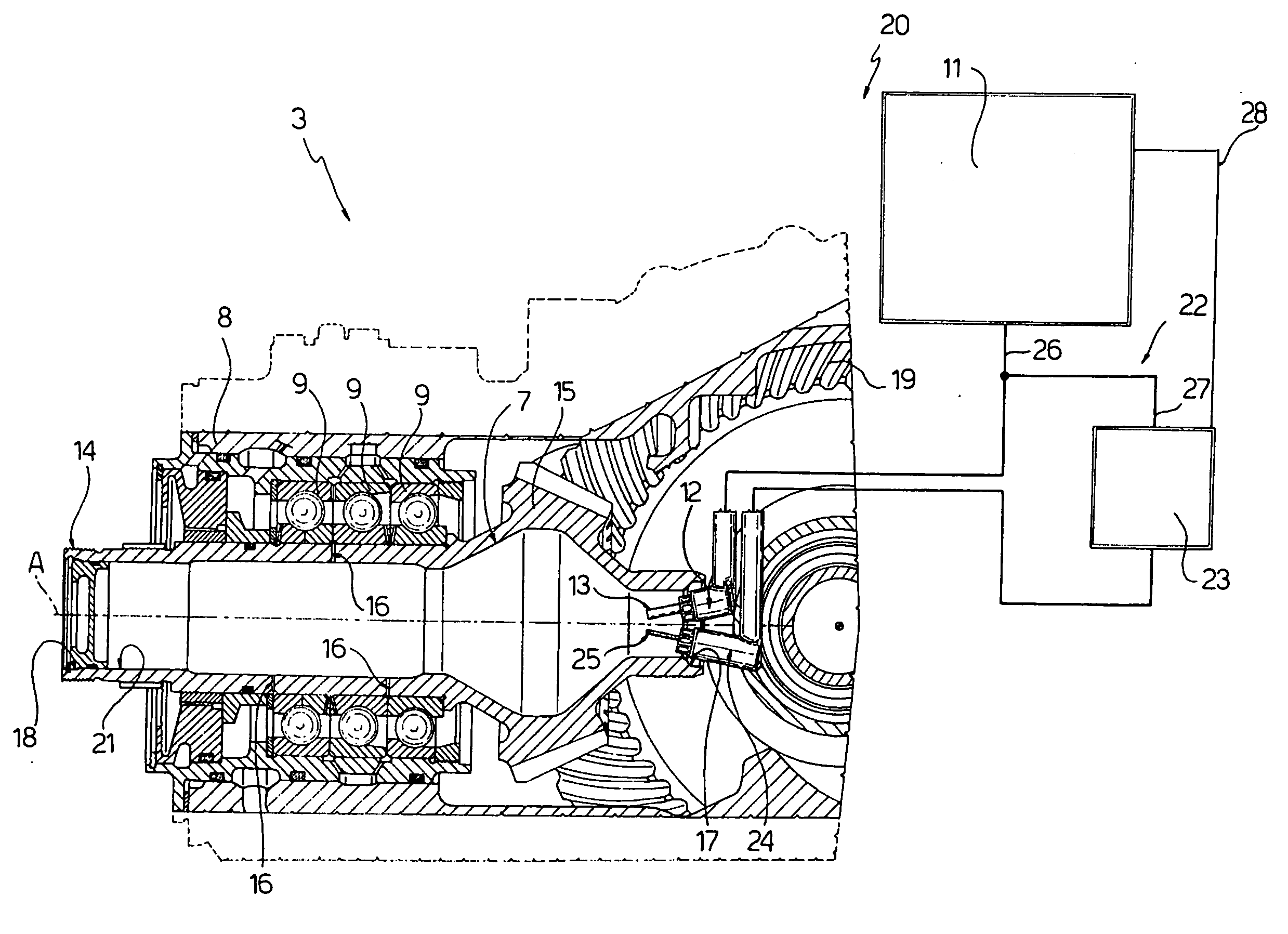
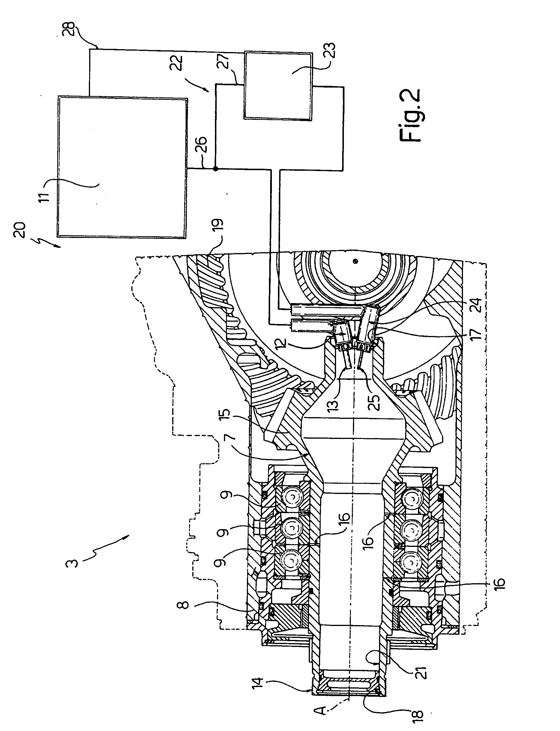
[0015]For which purpose, as shown in FIG. 2, helicopter 1 comprises a lubricating circuit 20 for feeding oil to transmissions 3, 6. More specifically, lubricating circuit 20 comprises a tank 11; and a number of nozzles 12 (only one shown) for feeding oil from tank 11 to respective transmissions 3, 6.

[0016]For the sake of simplicity, and purely by way of example, the following description refers to transmission 3...


PUM


Abstract

There is described a helicopter having a first member movable with respect to a second member; lubricated supporting means for supporting the first member with respect to the second member; and a primary lubricating circuit for lubricating the supporting means and in turn having primary storage means for accumulating a lubricating fluid, and primary fluid feed means for feeding the lubricating fluid to the supporting means; the helicopter also has an auxiliary lubricating circuit supplied continually by the primary storage means with a first lubricating fluid flow value, and itself continually supplying the supporting means with a second lubricating fluid flow value lower than the first value, so as to produce an auxiliary storage volume of lubricating fluid for use in the event of breakdown of the primary lubricating circuit.

Description

[0001]The present invention relates to a helicopter with an auxiliary lubricating circuit.BACKGROUND OF THE INVENTION[0002]As is known, helicopters are normally equipped with a number of transmissions for transmitting motion from one or more turbines to the main and / or tail rotor, and / or from the turbine to a number of accessory devices, i.e. for powering on-board equipment, for example.[0003]The transmissions normally comprise a first member movable with respect to a second member; and a number of bearings for supporting the first member with respect to the second member. Helicopters also comprise a circuit for supplying and lubricating the bearings with lubricating oil contained inside special tanks.[0004]In the event of damage to the lubricating circuit, the oil pressure falls, thus preventing operation of the transmission.[0005]In the industry, a need is felt to ensure, in such cases, correct operation of the transmission for a predetermined length of time, e.g. at least thirty ...

Claims


Application Information

Patent Timeline
IPC IPC(8): F01M1/20F16H57/04
CPCB64C27/006B64C27/12F16H57/0442F16H57/045F16C2361/61F16H57/0471F16H57/0495F16N7/38F16N9/02F16H57/0456
Inventor CARNELLI, SILVANOREGONINI, ROBERTOFORNI, MASSIMOGASPARINI, GIUSEPPE
Owner LEONARDO FINMECCANICA SPA
Why Eureka
Try Eureka