Devices Exhibiting Differential Resistance to Flow and Methods of Their Use

a technology of differential resistance and flow, applied in the direction of fluid pressure measurement, liquid/fluent solid measurement, peptide measurement, etc., to achieve the effect of the same resistan

Inactive Publication Date: 2009-03-19
CALIFORNIA INST OF TECH +1
View PDF9 Cites 20 Cited by
  • Summary
  • Abstract
  • Description
  • Claims
  • Application Information

AI Technical Summary

Benefits of technology

[0013]In this aspect, the invention features a microfluidic device including a channel having a structure, wherein the channel has a first resistance to pressure-driven flow in the absence of the structure, and the structure has a second resistance to pressure-driven flow that is higher than the first resistance. Desirably, the structure and the channel have substantially the same resistance to electric-field-driven flow. The structure, for example, includes a channel that is shorter, e.g., at most 10%, and wider than the first channel in the absence of the structure. This device may be employed in a method of manipulating fluids in a microfluidic device under applied electric fields, such that pressure-driven flow is substantially dampened.

Problems solved by technology

Structures in the device may cause anisotropy by lowering the permeability, e.g., to electric fields or pressure gradients, of at least a portion of the channel in which they are disposed.
Exemplary gels may exhibit reverse thermal gelation and / or be biocompatible.

Method used


Image

  • Devices Exhibiting Differential Resistance to Flow and Methods of Their Use
  • Devices Exhibiting Differential Resistance to Flow and Methods of Their Use
  • Devices Exhibiting Differential Resistance to Flow and Methods of Their Use

Examples


Embodiment Construction

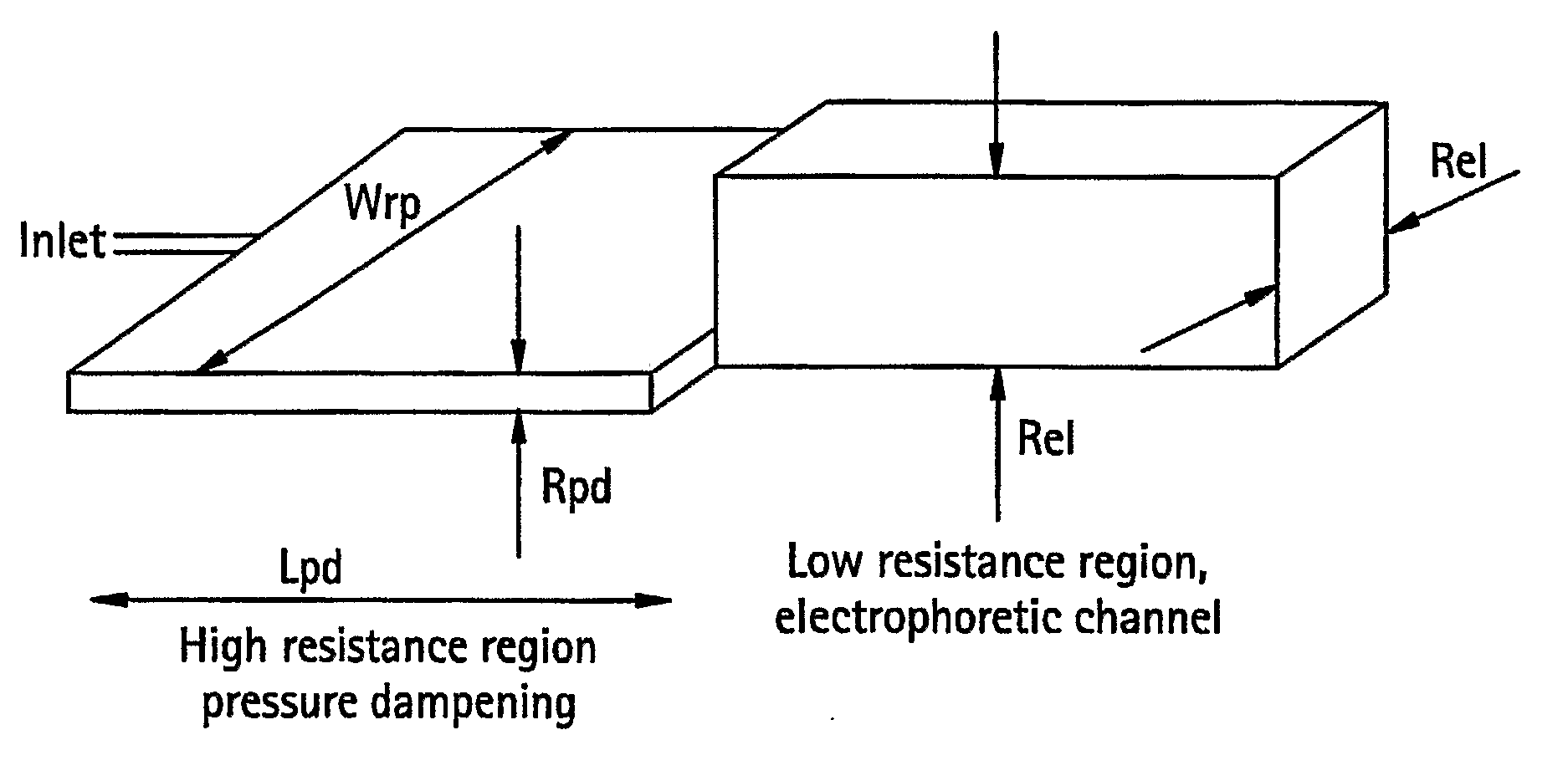
[0027]The invention provides devices that include structures that exhibit differential resistance to flow, e.g., under electric-field-driven flow or pressure-driven flow. Such devices allow for the miniaturization of sample distortion and the dampening of pressure-driven flow. In addition, the devices may also be employed for filtration of particulate samples or controlled contacting of reagents with other compounds, cells, or viruses.

Anisotropic Resistance to Flow

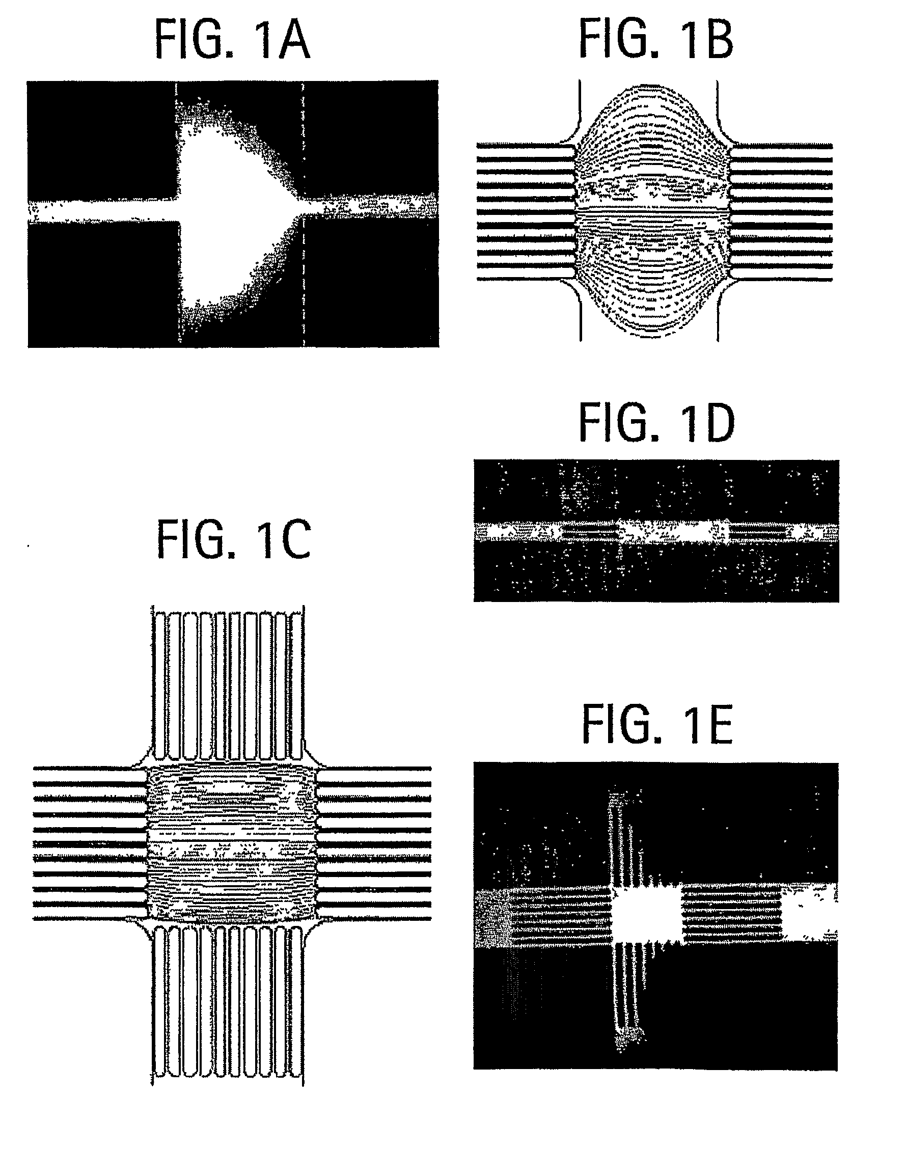
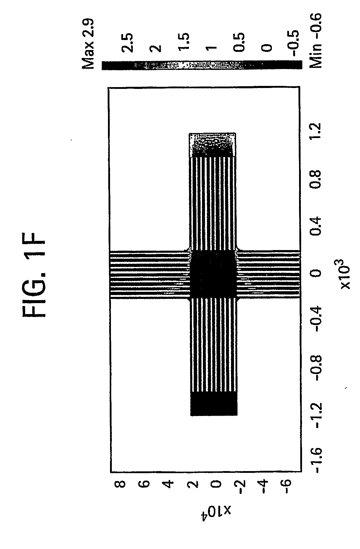
[0028]Electric Field. In this embodiment, the invention provides a microfluidic device capable of shaping an applied electrical field such that a plug of sample, i.e., a volume of fluid in a channel, can be introduced into an intersecting channel with low dispersion. The devices include a structure that produces anisotropic flow under an applied electric field. For example, the structure allows for greater flow parallel to the electric field than orthogonal to the electric field. Although illustrated with channels intersec...


PUM

PropertyMeasurementUnit
widthaaaaaaaaaa
widthaaaaaaaaaa
pHaaaaaaaaaa

Abstract

The invention features microfluidic devices that contain structures that impart differential resistance to a fluid flow. The structures are disposed adjacent to intersections of channels. Devices of the invention provide differential resistance, e.g., under electric-field-driven flow and pressure-driven flow.

Description

BACKGROUND OF THE INVENTION[0001]The invention relates to field of microfluidics.[0002]Microfluidic devices driven by electrical fields hold considerable potential for separation of complex mixtures. Minimizing injection volumes decreases the length of time required for separation, decreases the size of the separation device, and increases separation resolution. Improvements in minimizing injection size can therefore lead to improvements in microanalytical devices. For separations, electroosmotic flow usually gives better separation than pressure-induced flow, and it is easier to implement. Because flow fields typically scale linearly with the local electric field, microfluidic devices are well suited for modular design required for implementation of multiple fluidic tasks on a single two-dimensional platform.[0003]Established electrokinetic sample introduction methods rely on open channel geometries like double-T and double-L methods to define the injection zone or upon isoelectric...

Claims


Application Information

Patent Timeline
Patent Type & Authority Applications(United States)
IPC IPC(8): G01N27/447
CPCB01L3/502784B01L2200/0605B01L2200/0636B01L2200/0673G01N27/44743B01L2400/0421B01L2400/0487B01L2400/086B01L2300/0816C12M23/16C12M25/14
Inventor SQUIRES, TODD M.NAROVLYANSKY, MAX
Owner CALIFORNIA INST OF TECH
Why Eureka
Try Eureka