
A high-efficiency foam concrete foaming agent foaming machine

A foamed concrete and foaming agent technology, used in mixers, ceramic molding machines, fluid mixers, etc., can solve the problems of wasting high-pressure air, reducing compressive strength, and inability to continuously adjust the dilution ratio, and achieve improved quality. Effect

Active Publication Date: 2011-12-07
LUOYANG NORMAL UNIV
View PDF4 Cites 9 Cited by
  • Summary
  • Abstract
  • Description
  • Claims
  • Application Information

AI Technical Summary

Problems solved by technology

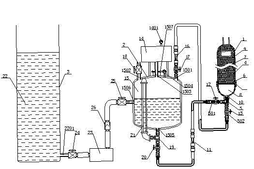
At present, the way to produce foam is to use high-pressure air and foaming agent diluent to mix in the mixing tube to form foam. The foaming system of the foaming machine has three structural defects: one is that the foaming agent stock solution cannot be mixed with water. Evenly mixed, the foaming agent stock solution in the form of micelles cannot be uniformly dispersed into water, and part of the foaming agent stock solution may still enter the foaming tube in the form of micelles, and the initial foaming agent diluent and air in the foaming tube The contact surface is small, and the uneven diluent will reach the stainless steel wire in the foam tube together with the air in the form of droplets or water flow. The resistance in the foam tube is unevenly distributed in the radial direction, and air channels are formed at the small resistance, and the resistance is large. The blowing agent diluent cannot fully form foam with the air, and the direct result is a waste of high-pressure air; second, the dilution factor cannot be adjusted continuously, and the dilution factor is ≤ 40; third, the length-to-diameter ratio of the foaming tube is too large, and the If the air flow rate is too small, the formed foam will be torn into micro-bubbles with a small diameter, that is, a "creamy" foam will be formed, and its large specific surface will prevent the concrete slurry from fully covering the surface of all the foam cells. , resulting in perforation of foamed concrete products and reduction of compressive strength

Method used


Image

  • A high-efficiency foam concrete foaming agent foaming machine
  • A high-efficiency foam concrete foaming agent foaming machine
  • A high-efficiency foam concrete foaming agent foaming machine

Examples


Embodiment 1

[0061] LC-01 foam concrete foaming agent, the expansion ratio is 4.0m 3 / kg, the dilution factor is 1:100.

[0062] The parameters of the present invention are as follows.

[0063] ①Air compressor: the maximum pressure is 0.6MPA, and the displacement is 50L / min.

[0064] ② Foaming agent diluent storage tank: the volume is 100L.

[0065] ③Foaming liquid dilution tank: the volume is 600L.

[0066] ④ Foam tube: the length L of the tube waist is 600mm; the inner diameter of the outlet is 20mm, the inner diameter of the middle part is 50mm, and the inner diameter of the inlet is 20mm.

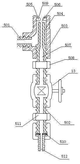
[0067] ⑤Spray mechanism: The outer diameter of the upper opening of the tee pipe is matched with the inner diameter of the spray port inlet of the foam pipe, and is connected with a screw; the outer diameter of the wrench bayonet 505 of the space adjustment screw 508 of the atomization chamber is 8mm, and the outlet diameter of the atomization chamber 4mm, air injection pipe 507 outlet diameter ...

Embodiment 2

[0103] LC-03 foam concrete foaming agent, the expansion ratio is 6.0m 3 / kg, the dilution factor is 1:100.

[0104] The parameters of the present invention are as follows.

[0105] ①Air compressor: the maximum pressure is 1.0MPA, and the displacement is 400L / min.

[0106] ② Foaming agent diluent storage tank: the volume is 400L.

[0107] ③Foaming liquid dilution tank: the volume is 1200L.

[0108] ④ Foam tube: the length L of the tube waist is 1200mm; the inner diameter of the outlet is 40mm, the inner diameter of the middle part is 120mm, and the inner diameter of the inlet is 40mm.

[0109] ⑤Spray mechanism: The outer diameter of the upper opening of the tee pipe is matched with the inner diameter of the spray port inlet of the foam pipe, and is connected with a screw; the outer diameter of the wrench bayonet 505 of the space adjustment screw 508 of the atomization chamber is 16mm, and the outlet diameter of the atomization chamber 8mm, the outlet diameter of air injecti...

Embodiment 3

[0145] A foam concrete foaming agent in a factory in my country, the expansion ratio is 1.6m 3 / kg, the dilution factor is 1:30.

[0146] The parameters of the present invention are as follows.

[0147] ①Air compressor: the maximum pressure is 1.0MPA, and the displacement is 400L / min.

[0148] ② Foaming agent diluent storage tank: the volume is 400L.

[0149] ③Foaming liquid dilution tank: the volume is 1200L.

[0150] ④ Foam tube: the length L of the tube waist is 1200mm; the inner diameter of the outlet is 40mm, the inner diameter of the middle part is 120mm, and the inner diameter of the inlet is 40mm.

[0151] ⑤Spray mechanism: The outer diameter of the upper opening of the tee pipe is matched with the inner diameter of the spray port inlet of the foam pipe, and is connected with a screw; the outer diameter of the wrench bayonet 505 of the space adjustment screw 508 of the atomization chamber is 16mm, and the outlet diameter of the atomization chamber 8mm, the outlet d...


PUM

PropertyMeasurementUnit
lengthaaaaaaaaaa

Abstract

The invention provides a high efficient foam concrete foaming agent foaming machine which comprises a foaming device, an air driving device and a foaming agent diluent feeding device, wherein the foaming device comprises a foaming pipe and a spraying mechanism; the air driving device comprises an air compressor and a foaming agent diluent storage tank; and the foaming agent diluent feeding deviceis connected with a liquid inlet pipe of the foaming agent diluent storage tank via a worm pump. By using the high efficient foam concrete foaming agent foaming machine provided by the invention, thedilution ratio of the foaming agent and the ratio of the diluent to the air can be randomly adjusted according to the instructions of the foaming agent and the hardness degree of the made foam so that the usage of the foaming agent is saved, compressed air is reduced and more stable foam with a larger diameter is formed.

Description

technical field [0001] The invention relates to a foaming machine, in particular to a device for efficiently mixing foam concrete foaming agent diluent and air to produce foam for foam concrete. Background technique [0002] Foamed concrete, also known as foamed cement, is made by introducing nitrogen, carbon dioxide, oxygen or air into the concrete slurry according to the application needs through chemical or physical means, mixing evenly, pouring, setting and curing. Among them, to introduce air into the concrete slurry in a physical way, it is necessary to mix the foam concrete foaming agent (hereinafter referred to as the foaming agent diluent) with air to make foam, and then mix the foam with the concrete slurry. At present, the way to produce foam is to use high-pressure air and foaming agent diluent to mix in the mixing tube to form foam. The foaming system of the foaming machine has three structural defects: one is that the foaming agent stock solution cannot be ...

Claims


Application Information

Patent Timeline
Patent Type & Authority Applications(China)
IPC IPC(8): B28B1/50
CPCB01F3/04446B01F15/0238C04B38/10B01F5/0415B01F5/043B01F5/0688B01F23/235B01F25/3121B01F25/31243B01F25/4521B01F35/71745
Inventor 王利亚李森兰刘献明李绍伟辛凌云
Owner LUOYANG NORMAL UNIV
Learn More