

Worker safety management system
- Summary
- Abstract
- Description
- Claims
- Application Information
AI Technical Summary
Benefits of technology
Problems solved by technology
Method used
Image

Examples
Embodiment Construction
)
[0040]A preferred embodiment of the worker safety management system according to the present invention is described in the following with reference to the appended drawings.
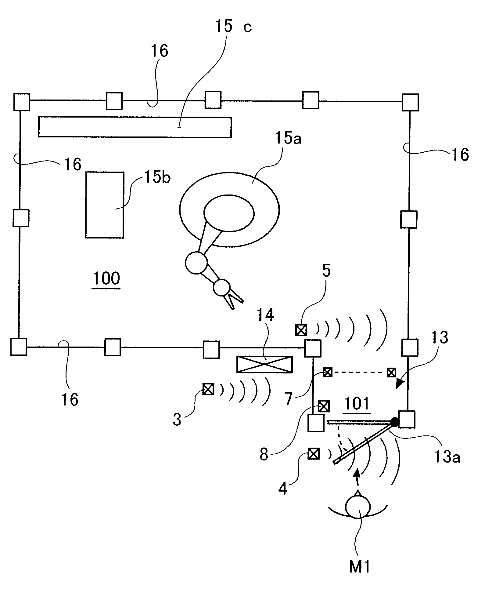
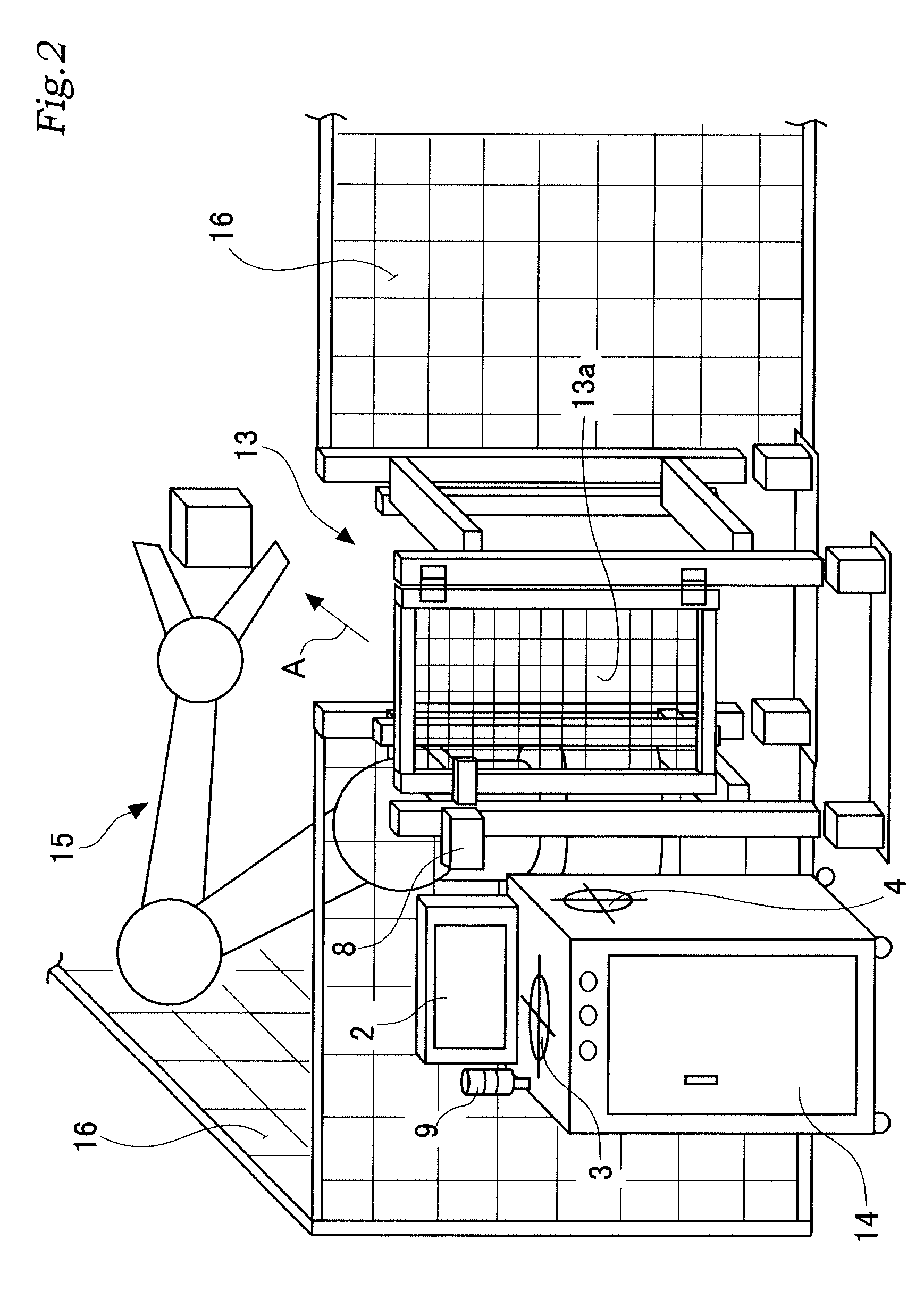
[0041]First of all, a work place to which the system of the present invention is applied is described in the following with reference to FIGS. 10 to 13. As shown in these drawings, this work place includes a work area 100 delimited by a protective fence 16. Substantially centrally placed in this work area 100 is a large robot 15a that can be used for various types of work, such as welding, picking, material working and assembling. In the illustrated embodiment, a press 15b for working work pieces and a conveyer 15c for transporting work pieces are installed adjacent to the robot 15a.
[0042]An access gate 13 is provided in a part of the protective fence 16 for gaining access into the work area. The illustrated gate 13 is provided with a small hall 101 that extends from the work area 100 and is provided with a doo...
PUM
 Abstract
Description
Claims
Application Information