Image capturing device

a technology of image capture and image, which is applied in the direction of instruments, television systems, color signal processing circuits, etc., can solve the problems of producing unnatural images, unable to see the facial expression of the person, and the inability to obtain the images desired by the photographer in some cases

Active Publication Date: 2009-03-19
OLYMPUS CORP
View PDF13 Cites 47 Cited by
  • Summary
  • Abstract
  • Description
  • Claims
  • Application Information

AI Technical Summary

Benefits of technology

[0010]The present invention has been made to solve the above-described problems, and an object of the present invention is to provide an image capturing device capable of providin

Problems solved by technology

However, in the image capturing devices which measure the luminance of the main subject and adjust the exposure level for the main subject, overexposure or underexposure may occur in portions other than the main subject in a scene having a large difference in luminance, producing an unnatural image when viewing the whole screen.
Further, in the image capturing devic

Method used


Image

  • Image capturing device
  • Image capturing device
  • Image capturing device

Examples


first embodiment

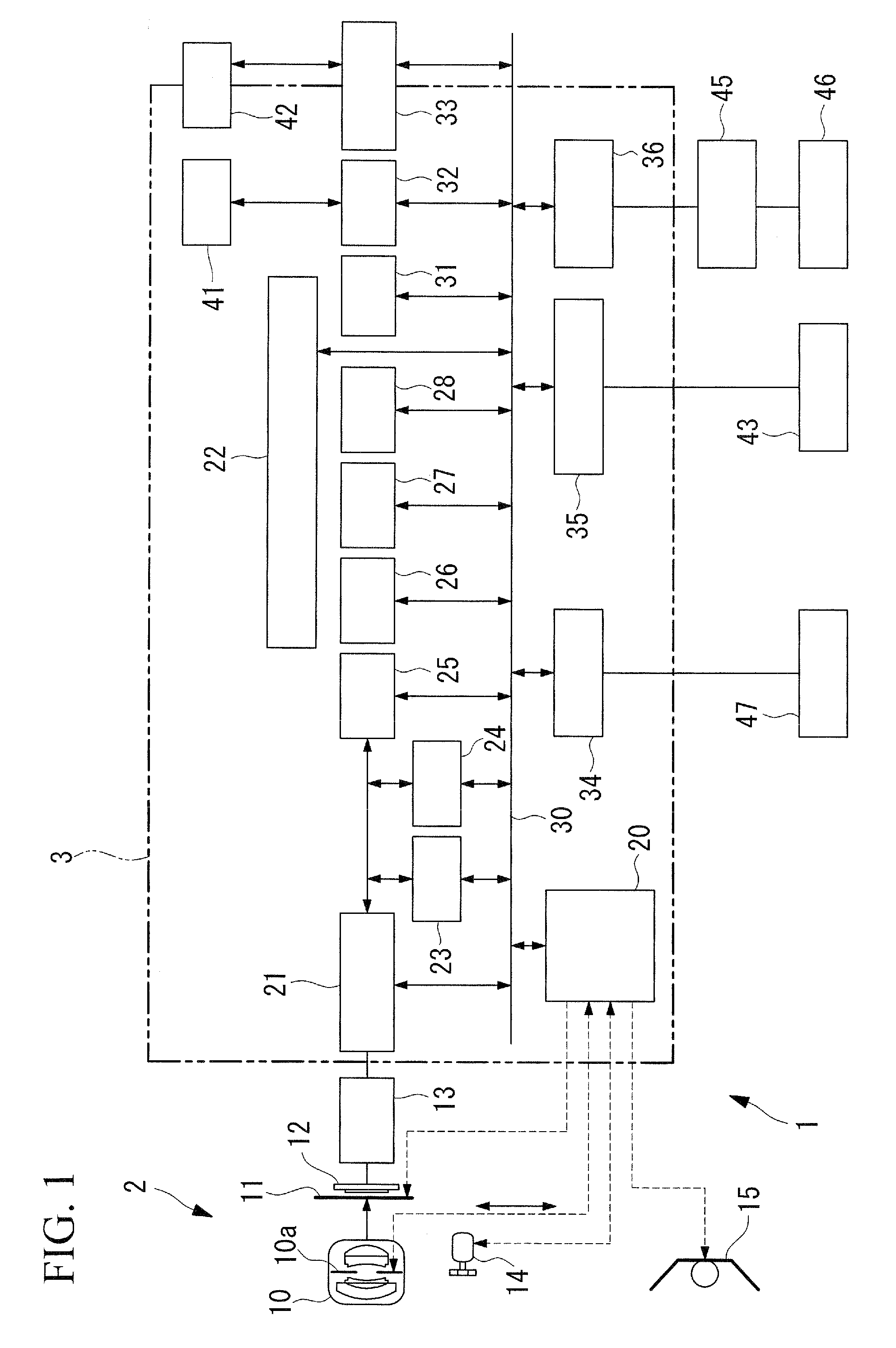
[0053]FIG. 1 is a block diagram showing a general configuration of an image capturing device 1 according to a first embodiment of the present invention. The image capturing device 1 of this embodiment is a digital camera, for example, and includes an image capturing unit 2 and an image processing device 3. The image capturing unit 2 includes a lens 10, a shutter 11, a CCD 12, a CCD control unit 13, a lens driving unit 14, and a stroboscope 15.

[0054]The lens 10 includes a photographic lens for focus adjustment and focal distance adjustment and an aperture stop 10a for aperture adjustment. The aperture stop 10a adjusts the depth of field and the brightness of light incident on the imaging area, according to a control instruction sent from a photography control unit 20. In inexpensive image capturing devices which do not require depth of field adjustment, however, the aperture stop 10a can be replaced, for example, with an ND filter used to adjust the amount of light, for the purpose o...

second embodiment

[0213]Next, a second embodiment of the present invention will be described with reference to FIG. 22.

[0214]According to the image capturing device 1 of the first embodiment, in the target luminance correction process (see FIG. 12A), performed in the photometric calculation process in Step SB8 of FIG. 3A, the lower threshold o_th_low and the upper threshold o_th_high, set in advance, are used to judge whether to correct the target luminance bv_p (see Step SF3 and corresponding steps of FIG. 12A). In an image capturing device of this embodiment, the lower threshold o_th_low and the upper threshold o_th_high are changed according to the gradation mode.

[0215]Hereinafter, the image capturing device of this embodiment will be described mainly in terms of the differences from those of the first embodiment, and a description of similarities will be omitted.

[0216]FIG. 22 is a diagram showing a sequence of an upper-and-lower-threshold determination process in which the lower threshold o_th_lo...

third embodiment

[0223]Next, a third embodiment of the present invention will be described with reference to FIG. 23.

[0224]As in the second embodiment, an image capturing device of this embodiment sets the upper threshold o_th_high and the lower threshold o_th_low in a manner different from that in the first embodiment. Specifically, the upper threshold o_th_high and the lower threshold o_th_low are changed according to any of three cases: when a face was detected in the through-the-lens image; when a face was not detected but distance measurement was able to be performed; and when neither a face was detected nor distance measurement was able to be performed.

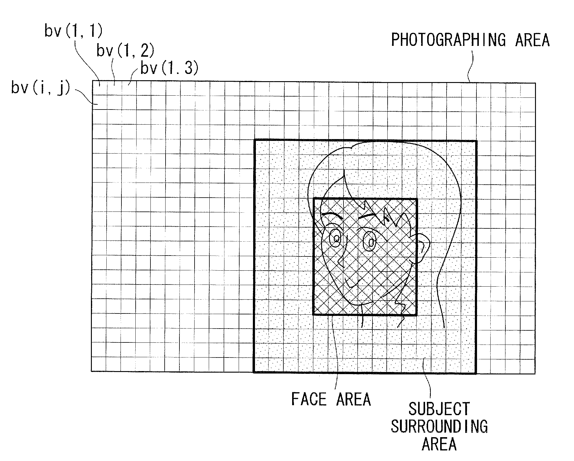
[0225]FIG. 23 is a graph showing an example method of setting the upper threshold o_th_high and the lower threshold o_th_low according to this embodiment. In FIG. 23, the vertical axis indicates thresholds and the horizontal axis indicates the area ratio of the subject area to the photographing area. As shown in FIG. 23, when a face was detected...


PUM


Abstract

An image having the image quality desired by a photographer is provided by minimizing overexposure or underexposure, making the dynamic range wide, and specifying an optimum brightness level for a main subject. An image capturing device includes a subject detecting unit which detects a main subject in an image obtained before actual photographing; a subject luminance information acquiring unit which obtains luminance information; a luminance distribution calculating unit which calculates a luminance distribution of each of multiple areas; a target luminance calculating unit which determines a target luminance; a target luminance correcting unit which corrects the target luminance; and an exposure condition determining unit which determines an exposure condition for the actual photographing, in which the target luminance correcting unit includes a criterial range determining unit which determines the criterial range; and a correction amount determining unit which determines a correction amount by using the difference between the target luminance and the luminance of the main subject.

Description

BACKGROUND OF THE INVENTION[0001]1. Field of the Invention[0002]The present invention relates to an image capturing device such as a digital camera.[0003]This application is based on Japanese Patent Application No. 2007-240890, the content of which is incorporated herein by reference.[0004]2. Description of Related Art[0005]Image capturing devices have been conventionally known which measure the luminance of a main subject and adjust the exposure level for the main subject.[0006]Image capturing devices have also been known which use subject luminance distribution information to perform exposure adjustment and a gradation conversion process in order to prevent overexposure or underexposure from occurring in the entire screen and have a wide dynamic range (see, for example, Japanese Unexamined Patent Application, Publication No. 2000-184272, Japanese Unexamined Patent Application, Publication No. 2004-229054, and Publication of Japanese Patent No. 3478769).[0007]However, in the image ...

Claims


Application Information

Patent Timeline
IPC IPC(8): H04N9/68
CPCH04N5/23212H04N5/23219H04N5/2354H04N5/2353H04N5/2351H04N23/611H04N23/71H04N23/73H04N23/74
Inventor SHIMIZU, SAORI
Owner OLYMPUS CORP
Why Eureka
Try Eureka