
System and methods for dynamically generating earth position data for overhead images and derived information

a dynamic generation and overhead image technology, applied in the field of system and methods for dynamic generation of earth position data, can solve the problems of inability to apply a dem re-computed inability to leverage technology to process information digitally in a way conducive to modern computer environments, and inability to re-apply to a dem re-compute over the same area, so as to improve the accuracy of “product” imagery

Active Publication Date: 2009-03-19
OBSERVERA
View PDF3 Cites 31 Cited by
  • Summary
  • Abstract
  • Description
  • Claims
  • Application Information

AI Technical Summary

Benefits of technology

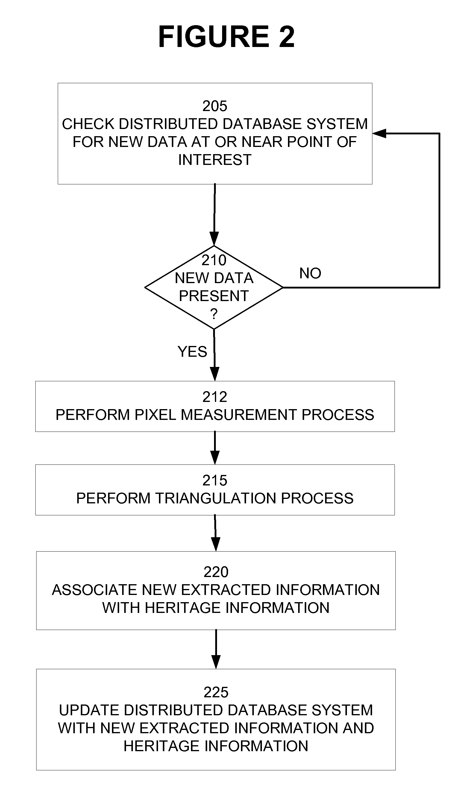
[0007]4) Triangulation results are reviewed for quality. Triangulation is the process of improving the accuracy of imagery through measurements and mathematical computations. This is typically performed using a bundle block adjustment process.
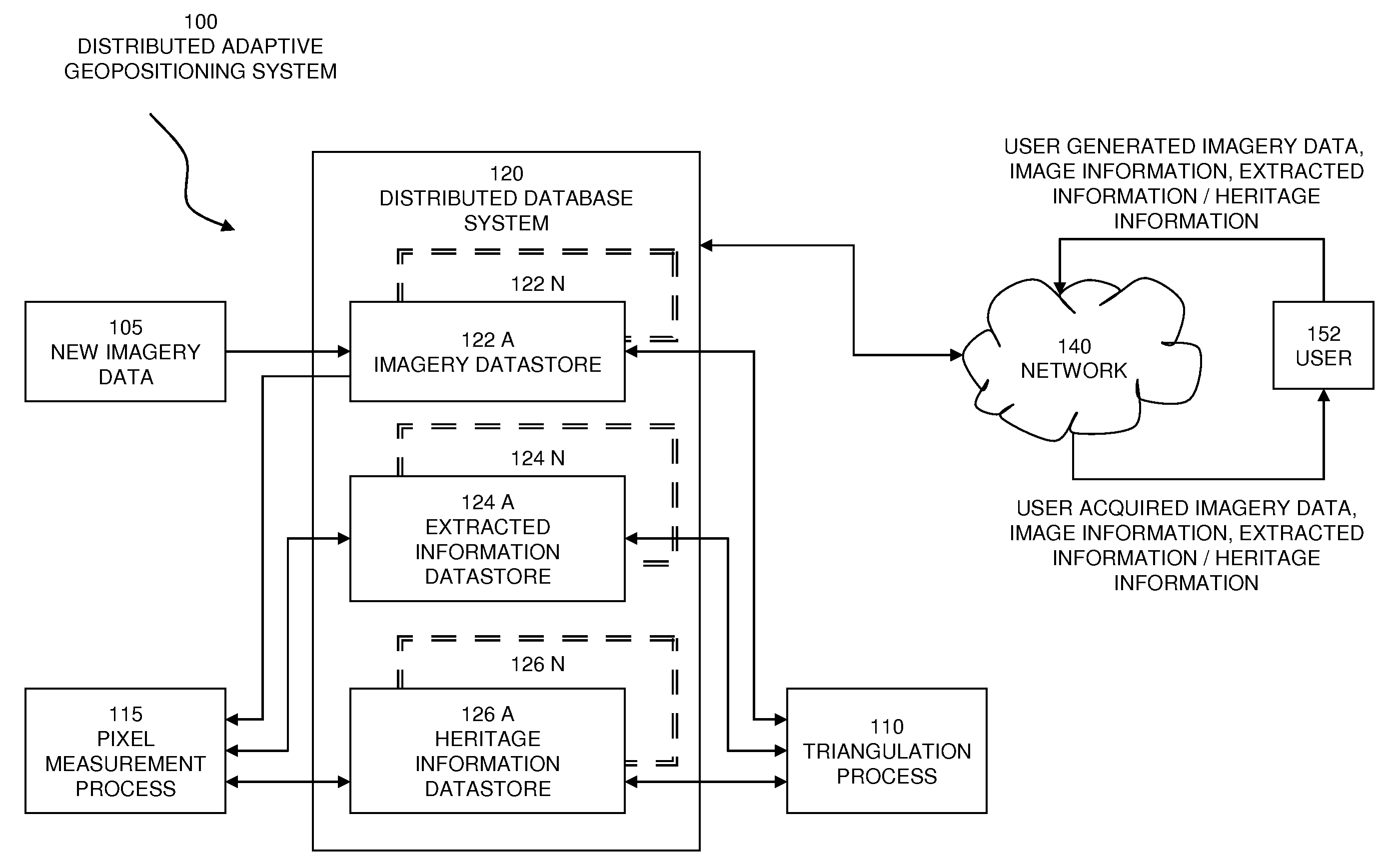
[0013]The “product approach” is inherently inefficient. For a particular product, the imagery is triangulated using only the imagery collected for that product, such as 1° by 1° cells, then the information used to perform the triangulation (referred to herein as a part of “heritage information”) is either 1) not retained in the first place, 2) is gathered but thrown away upon process completion, or 3) is kept in the hands of a select few in one small part of the overall process. This heritage information has value and can be combined with other similar information to improve the accuracy of “product” imagery, as well as future and past imagery collected over the same area.

Problems solved by technology

In general, they are digital versions of analog processes that fail to leverage technologies to process information digitally in a way conducive to modern computer environments.
1) Imagery is collected. The imagery may go to one or more libraries for storage. These libraries are geographically separated, and may be network-topologically separated, as well. For instance, each commercial imagery provider has its own storage, and some imagery may be duplicated on Government libraries at various security levels. Each image will have image support metadata containing sensor model parameters and often error estimates.
2) Image measurements of tie-points and control points are made. Additional imagery must be accessed to measure tie-points and control points. Sometimes tie-points or control points have been previously measured on the imagery. These measurements are performed in “image space.”
3) A photogrammetric triangulation using weighted least squares (WLS) adjustment is run. This adjusts the images for consistency and seamlessness over the project area.
4) Triangulation results are reviewed for quality. Triangulation is the process of improving the accuracy of imagery through measurements and mathematical computations. This is typically performed using a bundle block adjustment process.
5) Final adjustments are applied to imagery support metadata and tie point coordinates. This can be in the form of changes to initial or previous sensor model parameter values or in the form of additional sensor or geometry model parameters. The process often includes the update of error estimate information for the sensor model parameters and the tie points used in the triangulation process.
6) Derivative products are made. These include stereo products, such as Digital Point Positioning Data Base (DPPDB), monoscopic products, such as Controlled Image Base (CIB) and other orthorectified products, elevation data, such as Digital Terrain Elevation Data (DTED), and feature vector data.
Even though these edits involve feature vector-like extractions of lines and polygons, they are not retained and so they cannot be re-applied to a DEM re-computed over the same area.
The “product approach” is inherently inefficient.
Either the old data is completely discarded and replaced with the new data, or an attempt is made to conflate the ground coordinates from the older and new data, which is a difficult process.
Although some extraction can be automated, it still requires labor-intensive manual intervention.
Current methods do not leverage off the labor put into the production of previous DEMs and vectors, including their editing.

Method used


Image

  • System and methods for dynamically generating earth position data for overhead images and derived information
  • System and methods for dynamically generating earth position data for overhead images and derived information
  • System and methods for dynamically generating earth position data for overhead images and derived information

Examples


Embodiment Construction

[0026]For the purposes of this Application, the following terms have the meaning ascribed to them:

[0027]“Imagery data” means the raw data in pixel form that defines the image.

[0028]“Image information” means data about an image such as the date the image was taken, the sensor, vehicle, and platform used to capture the image, sensor model support data parameters, intrinsic error data, and an image identifier.

[0029]“Heritage information” means any information relevant to the computation of extracted information. This includes, but is not limited to, image pixel measurements and error estimates, and the record of DEM edits performed over an area.

[0030]“Extracted information” means information derived from one or more images through manual or automated means. This includes, but is not limited to, feature vectors consisting of individual ground points and vertexes of line, polygon, and 3-D volume features; DEM posts and DEM edits, such as breaklines, monotonic drainage lines, and polygons...


PUM


Abstract

Distributed adaptive geopositioning includes an objective architecture for imagery geopositioning. The positioning is distributed to fulfill the need to perform accurate geopositioning whenever and wherever it is needed. The positioning is adaptive to implement the idea that geopositioning is a dynamic, not static, quality of geospatial intelligence, for which accuracy can be improved over time as more data is collected and ingested. Focus is placed on the need for improved geopositioning throughout all areas of geospatial intelligence exploitation, not just for specific products or tools. Legacy data is re-computed to align with the geopositioned imagery and also benefits from improved accuracy.

Description

CROSS REFERENCE TO RELATED APPLICATIONS[0001]This application claims the benefit of Provisional Application No. 60 / 949,620 filed Jul. 13, 2007. The 60 / 949,620 application is incorporated by reference herein, in its entirety, for all purposes.BACKGROUND AND SUMMARY[0002]Digital geospatial production processes today are highly influenced by analog processes before computers. In general, they are digital versions of analog processes that fail to leverage technologies to process information digitally in a way conducive to modern computer environments.[0003]The present state of the art in photogrammetric production utilizes product-centric approaches that focus on imagery collected with a fixed spatial and temporal extent. A typical flow is set forth below:[0004]1) Imagery is collected. The imagery may go to one or more libraries for storage. These libraries are geographically separated, and may be network-topologically separated, as well. For instance, each commercial imagery provider h...

Claims


Application Information

Patent Timeline
Patent Type & Authority Applications(United States)
IPC IPC(8): G06K9/00
CPCG01S5/00G01C11/00
Inventor JAMISON, TODDBRESNAHAN, PAULYESHNIK, MARK
Owner OBSERVERA
Learn More