Vertical axis sail-type windmill power transfer device

Inactive Publication Date: 2009-03-19
SEMOV SEVDALIN
View PDF4 Cites 20 Cited by
  • Summary
  • Abstract
  • Description
  • Claims
  • Application Information

AI Technical Summary

Benefits of technology

[0007]The purpose of the vertical axis sail type windmill power transfer device proposed in this invention is to transform multi-directional wind power to the mechanical power needed to drive an electric generator. The sail dragging effect is achieved by using plurality of pairs of blades that are permanently attached to freely rotating horizontal rods penetrating the vertical output shaft. Each blade is preferably in airfoil shape and is fastened symmetrically on each side of the horizontal rod by a spring-type safety mechanism. Each blade is oriented at 90 degrees with respect to the other. The center of the we

Problems solved by technology

Also, HAWGs do not orient themselves toward the wind, which is their main deficiency, and may be less efficient harvesting winds closer to the ground surface where wind is slower.
HAWGs used nowadays in modern wind farms tend to have

Method used


Image

  • Vertical axis sail-type windmill power transfer device
  • Vertical axis sail-type windmill power transfer device
  • Vertical axis sail-type windmill power transfer device

Examples


Embodiment Construction

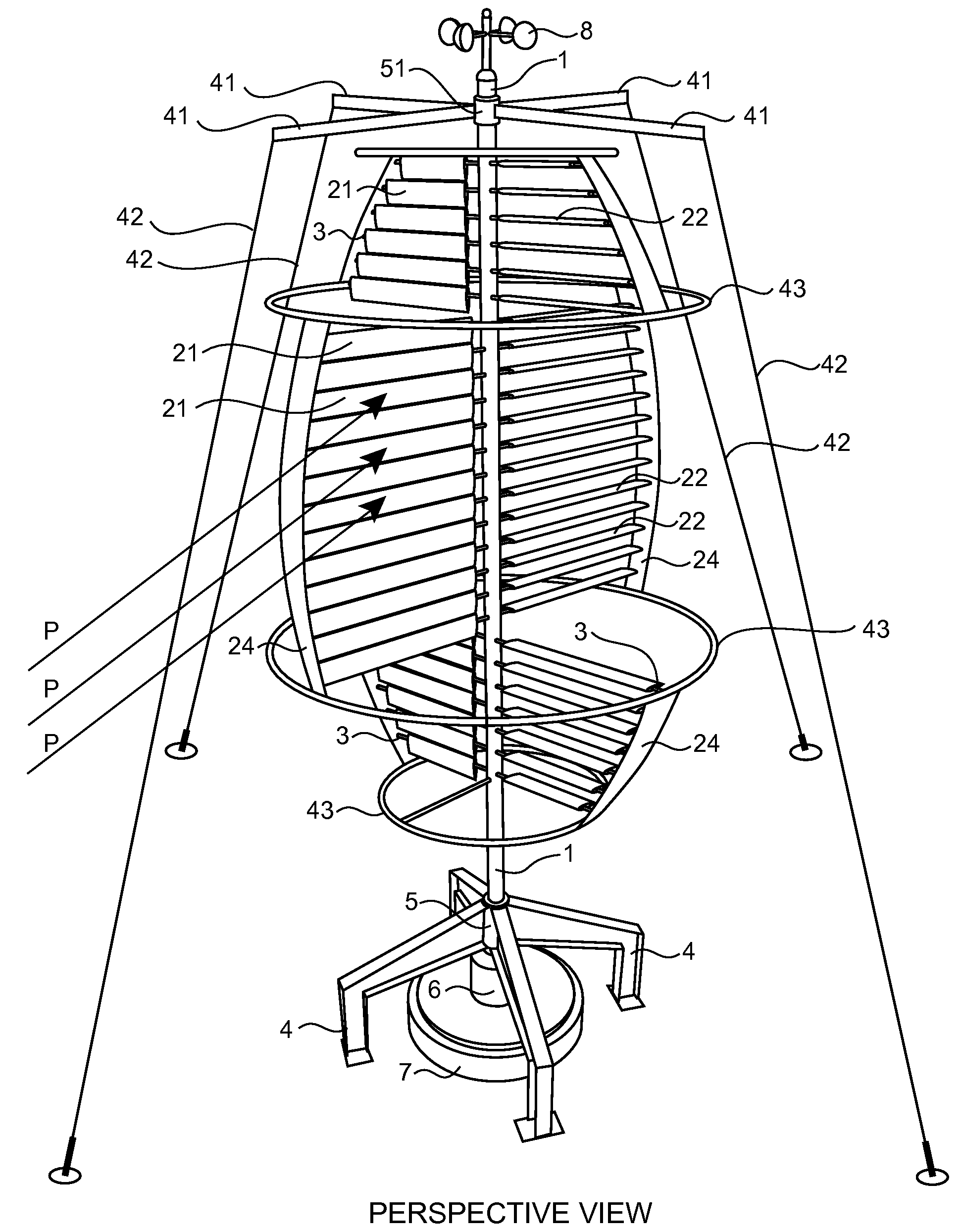
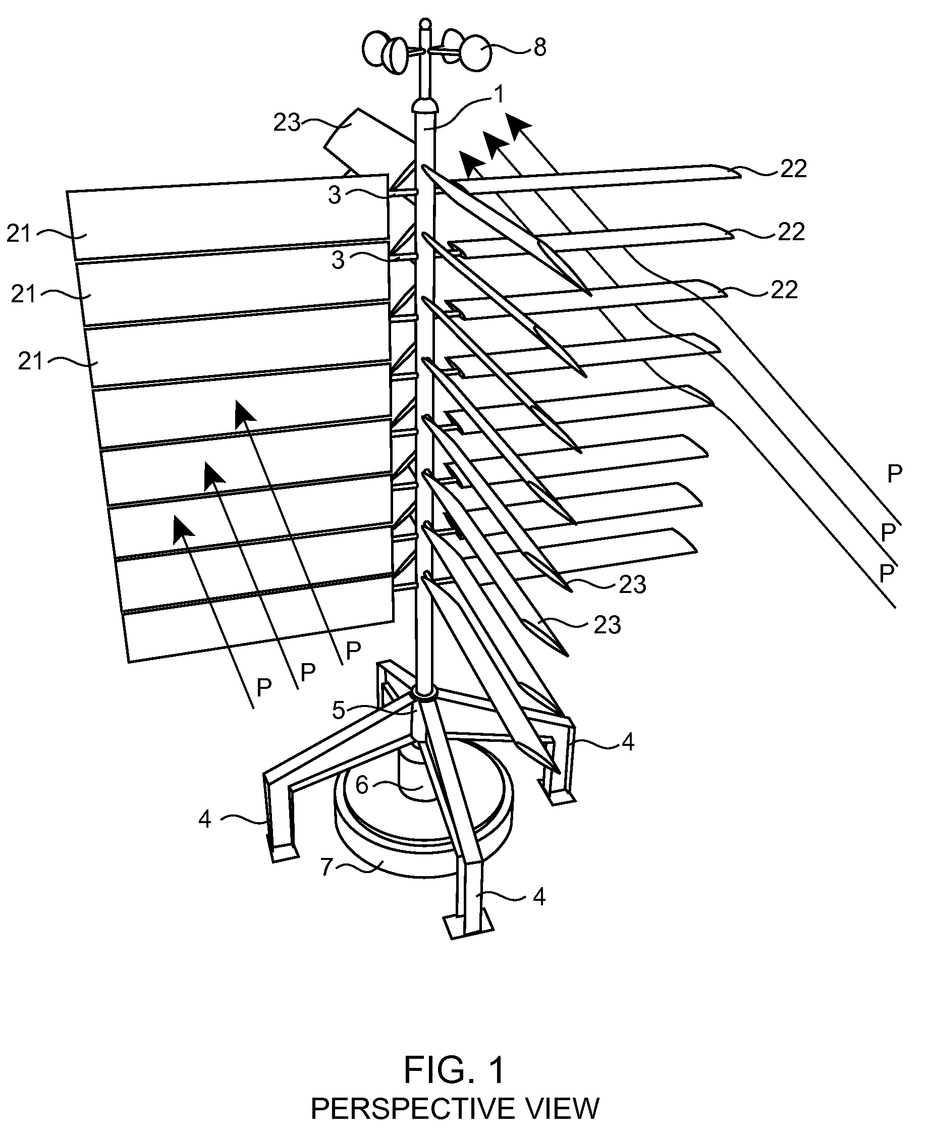
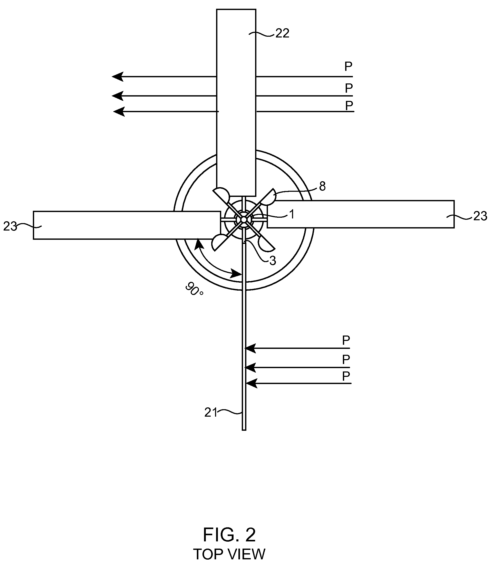
[0028]FIG. 1 presents a perspective view of the basic embodiment of the present invention, a vertical axis sail-type windmill power transfer device for efficiently harvesting wind power by increasing the effective surface of interaction with the wind (P). This embodiment describes the basic principles on which this invention is based. The sail dragging effect is achieved by using plurality of pairs of blades (21, 22, 23) that are permanently attached to freely rotating horizontal rods (3) penetrating the vertical output shaft (1). Each blade is preferably in airfoil shape and is fastened symmetrically on each side of the horizontal rod (3) by a spring-type safety mechanism (9FIG. 7a,b). Each blade is oriented at 90 degrees with respect to the other. The center of the weight (W) of each blade is offset from the pivot which causes the blades to constantly self-adjust when impacted by wind (P) coming from any direction so that one blade assumes a driving position (21) when the opposite...


PUM


Abstract

This invention relates to a vertical axis sail-type windmill power transfer device for efficiently harvesting wind power by increasing the effective surface of interaction with the wind where the sails are formed by a plurality of pairs of blades permanently attached to freely rotating horizontal rods penetrating the vertical output shaft with pivot offset of the center of the weight which causes the blades to self-adjust when impacted by wind so that one blade assumes a driving position while the other—a leeward position. The invention has a modular-type structure which permits for a variety of configurations and allows for photovoltaic cells to be placed on the blades in order to complement the production of wind energy with solar energy.

Description

REFERENCE TO RELATED APPLICATIONS[0001]U.S. Pat. No. 7,413,404 B2 Aug. 19, 2008BACKGROUND OF THE INVENTION[0002]This invention relates to a sail-type windmill power transfer device for producing electrical or mechanical power in any environment where wind is present. Thus, this invention pertains to the field of natural renewable energy.[0003]The windmill as a device has been utilized by mankind for hundreds of years because of its usefulness in converting wind power into mechanical power and, more recently, into electrical power.[0004]Generally, wind generators can be subdivided into two categories—horizontal axis wind generators (HAWG) and vertical axis wind generators (VAWG), depending on the orientation of the main rotor shaft. A major difference between these subcategories is the fact that, in the case of HAWGs, the main rotor and electrical generator are positioned at the top of the windmill tower, while in the case of VAWGs they are placed close to or on the ground, thus simp...

Claims


Application Information

Patent Timeline
IPC IPC(8): F03D3/00H01L31/042F03D9/00
CPCF03D3/02Y02E10/74F03D3/067F03D3/068
Inventor SEMOV, SEVDALIN
Owner SEMOV SEVDALIN
Why Eureka
Try Eureka