
Manifold designs, and flow control in mulitchannel microchannel devices

a microchannel device and manifold technology, applied in the direction of liquid gas reaction of thin film type, hydrogen/synthetic gas production, hydrogen, etc., can solve the problems of insufficient design for obtaining highly equal flow from a header, adding to the flow distribution challenge, etc., to achieve equal flow distribution, lower manifold pressure drop, and reduce costs

Inactive Publication Date: 2009-03-19
VELOCYS INC
View PDF35 Cites 18 Cited by
  • Summary
  • Abstract
  • Description
  • Claims
  • Application Information

AI Technical Summary

Benefits of technology

[0042]Any of the articles described herein may have multiple layers and repeating sets of layers (repeating units). For example, 2, 10, 50 or more repeating units within a laminate. This multiplicity, or “numbering up” of layers creates added capacity of microchannel laminated devices.
[0043]Various embodiments of the present invention may possess advantages such as: lower costs, more equal flow distribution in a multichannel array, lower manifold pressure drop, or additional heat transfer.GLOSSARY
[0047]A “bump” is an obstruction or area of increased channel wall roughness that reduces mass flow rate through a channel under typical operating conditions.
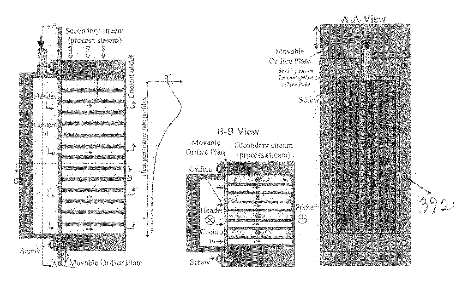
[0059]A “gate” comprises an interface between the manifold and two or more connecting channels. A gate has a nonzero volume. A gate controls flow into multiple connecting channels by varying the cross sectional area of the entrance to the connecting channels. A gate is distinct from a simple orifice, in that the fluid flowing through a gate has positive momentum in both the direction of the flow in the manifold and the direction of flow in the connecting channel as it passes through the gate. In contrast, greater than 75% of the positive momentum vector of flow through an orifice is in the direction of the orifice's axis. A typical ratio of the cross sectional area of flow through a gate ranges between 2-98% (and in some embodiments 5% to 52%) of the cross sectional area of the connecting channels controlled by the gate including the cross sectional area of the walls between the connecting channels controlled by the gate. The use of two or more gates allows use of the manifold interface's cross sectional area as a means of tailoring manifold turning losses, which in turn enables equal flow rates between the gates. These gate turning losses can be used to compensate for the changes in the manifold pressure profiles caused by friction pressure losses and momentum compensation, both of which have an effect upon the manifold pressure profile. The maximum variation in the cross-sectional area divided by the minimum area, given by the Ra number, is preferably less than 8, more preferably less than 6 and in even more preferred embodiments less than 4.

Problems solved by technology

Although these devices may offer many advantages, new designs and differing flow characteristics within these devices create challenges for creating new methods and designs for controlling flow, particularly flow through a manifold and several connecting channels.
Thus, a large microchannel processing device could have relatively small pressure drops at high overall flow rate, adding to the flow distribution challenge due to low flow resistance.
Calculations based on this design, as described in the Examples section, show that this design is inadequate for obtaining highly equal flow from a header through all connecting channels.

Method used


Image

  • Manifold designs, and flow control in mulitchannel microchannel devices
  • Manifold designs, and flow control in mulitchannel microchannel devices
  • Manifold designs, and flow control in mulitchannel microchannel devices

Examples


example 1

Comparative Calculated Example

[0301]Calculations have been conducted based on a design shown in FIGS. 51 to 64 of Golbig published patent application US 2002 / 0106311A1. In this design, a fluid flows into two separate headers of the same dimensions. The header intersects at a right angle with the ends of connecting channels of varying widths; the widths varying from widest at the start of the header to the narrowest channel at the end. The object of this design was to enable “viscous fluids to be processed in parallel fluid channels with substantially equivalent residence time distributions.” The varying channel width tailors the connecting channel flow resistance to compensate for the differences between the header and footer pressure for a given fluid viscosity and flow rate, adding resistance to channels with larger pressure difference driving forces and less resistance to those with lower pressure difference driving force.

[0302]While the publication does not specifically describe...

example 2

[0315]This example describes the predicted performance of the SMR module flow distribution discussed earlier in the application.

[0316]In this design, the gate widths grow wider as the length of a sub-manifolds upstream length increases, and the width of a sub-manifold increases as the sub-manifold's upstream length increases. By using the widths of both sub-manifolds and gates within sub-manifolds, the overall pressure drop seen in each sub-manifold was equalized in both air and fuel header M2M manifolds. The sub-manifold with the shortest path length (#1) across the shim has the thinnest sub-manifold width and the thinnest gates, while the sub-manifold with the longest path across the shim (#6) has the widest sub-manifold width and widest gates. The relative dimensions for the manifolds are given below in Table 1.

TABLE 1Dimensions for the combustion M2M air and fuelsub-manifolds listed per sub-manifold number.Sub-M2MWidth of air GatesWidth of Fuel Gatesmanifoldchannel(inches)(inche...

example 3

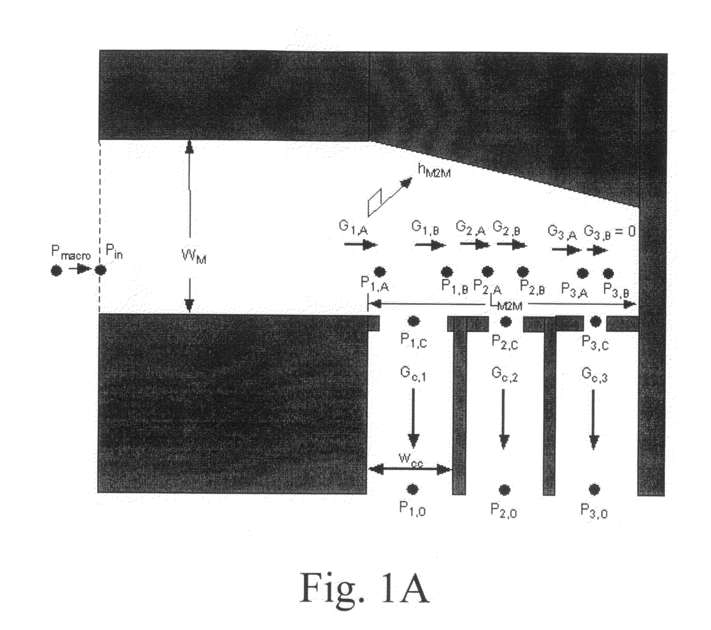
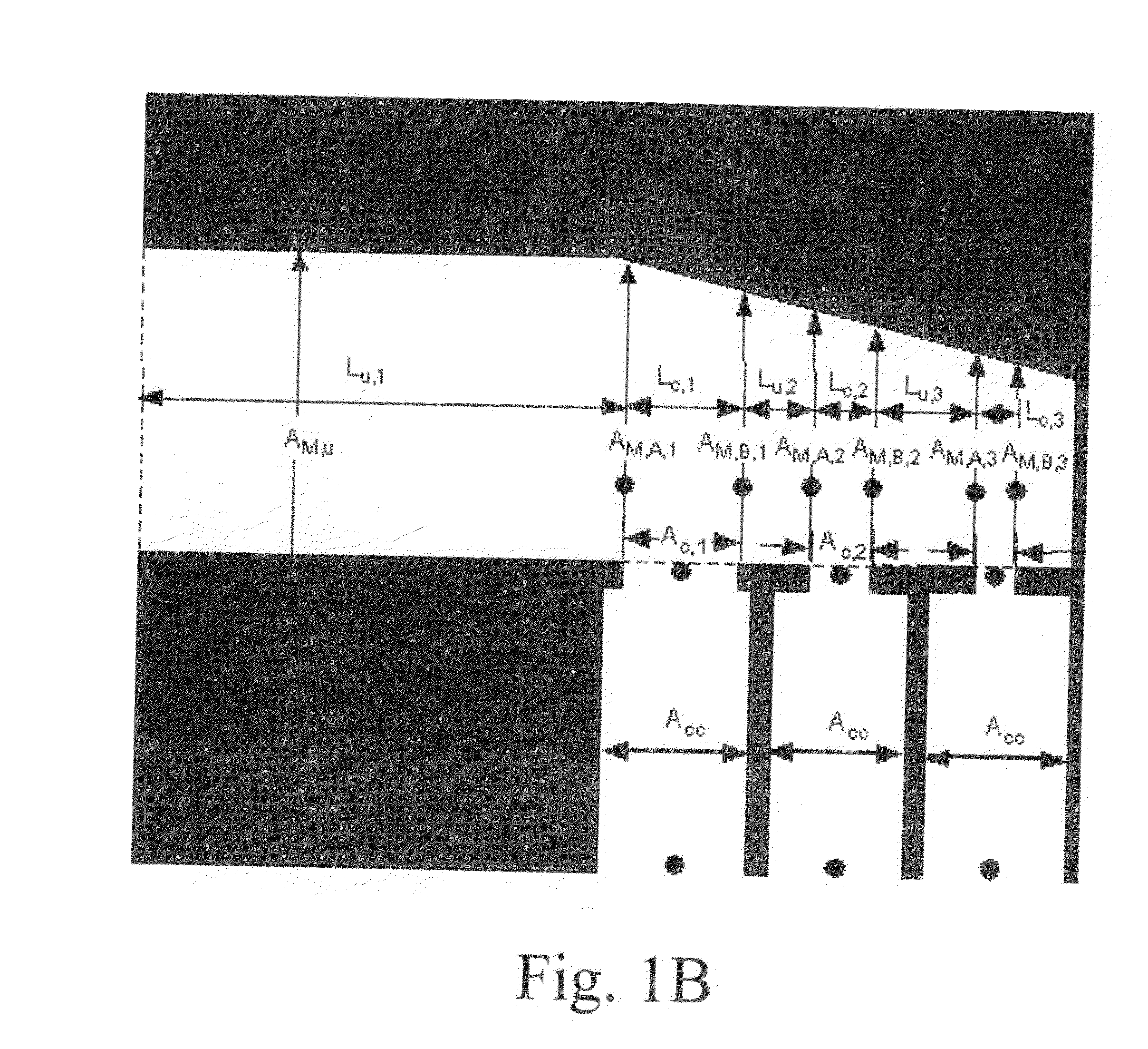
[0318]This example is a calculated example based on a sub-manifold that has the following features: L-manifold header, like that described; constant width, height of M2M manifold; 3 “gates”, each serving four connecting channels downstream of the distribution section; and high momentum flow (Entrance Mo=0.7>>0.05). The conditions are: an outlet pressure of 1 atm (101325 Pa); air flow of 38.22 SLPM; and 20° C.

The header M2M manifold dimensions are:[0319]0.041″ height, made from a 0.017″ and a 0.023″ shims and a 0.001″ tall gasket[0320]0.400″ wide for the entire manifold (Wm)[0321]AM=1.04×10⁻⁵ m2 [0322]Lengths:[0323]From macro manifold connection to first gate: 1.250″ (=Lu,1)[0324]From macro manifold connection to end of the manifold 3.700″[0325]Lengths for friction losses:[0326]Lc,1=0.270″[0327]Lc,2=0.250″[0328]Lc,3=0.245″[0329]Lu,1=1.250″[0330]Lu,2=0.680″[0331]Lu,3=0.692″

Gate and distribution section dimensions:[0332]Center position of gates from macro manifold:[0333]1st: 1.410″[033...


PUM

PropertyMeasurementUnit
dimensionsaaaaaaaaaa
area ratioaaaaaaaaaa
heightaaaaaaaaaa

Abstract

Novel manifolds and methods of flow through manifolds are described. Apparatus and techniques are described in which flow from a relatively large volume header is equally distributed to process channels. Methods of making laminated, microchannel devices are also described.

Description

[0001]In recent years there has been intense industrial and academic interest toward developing microscale devices for chemical processing. A recent review of microscale reactors, containing 236 citations, has been provided by Gavrilidis et al., “Technology And Applications Of Microengineered Reactors,” Trans. IChemE, Vol. 80, Part A, pp. 3-30 (January 2002). Microscale chemical processors, which are characterized by fluid channel dimensions of about 5 mm or less, can provide unique advantages due to short heat and mass transfer distances, and, in some instances, different flow characteristics. Although these devices may offer many advantages, new designs and differing flow characteristics within these devices create challenges for creating new methods and designs for controlling flow, particularly flow through a manifold and several connecting channels. In particular, the small channel dimensions that give rise to improved heat and mass transport can often be in the laminar flow re...

Claims


Application Information

Patent Timeline
Patent Type & Authority Applications(United States)
IPC IPC(8): B01J19/00F17D1/00C01B3/38F15D1/00F15D1/04
CPCB01J19/0093Y10T436/2575B01J2219/00891B01J2219/00995C01B3/384C01B2203/0233C01B2203/0811C01B2203/0822F15D1/001F15D1/04F28F3/08F28F2260/02B01J2219/00781B01J2219/0086B01J2219/00783Y10T137/0318Y10T137/85938Y02P20/10
Inventor FITZGERALD, SEAN P.TONKOVICH, ANNA LEEARORA, RAVIQIU, DONGMINGYUSCHAK, THOMAS D.SILVA, LAURA J.ROGERS, WM. ALLENJAROSCH, KAISCHMIDT, MATTHEW B.
Owner VELOCYS INC
Learn More