Fiber optic fuel detection system

a technology of fuel detection and fiber optics, applied in the direction of liquid/fluent solid measurement, fluid pressure measurement, machine/engine, etc., can solve the problems of aircraft out of service for maintenance and aircraft out of commission for this type of maintenan

Inactive Publication Date: 2009-03-19
THE BOEING CO
View PDF4 Cites 23 Cited by
  • Summary
  • Abstract
  • Description
  • Claims
  • Application Information

AI Technical Summary

Benefits of technology

[0007]The advantageous embodiments of the present invention provide a method and apparatus for an optical fuel detection system. The optical fuel detection system comprises an outer tube, and inner tube, and a set of optical fibers. The outer tube has a reflective inner surface capable of reflecting light and is configured to allow a liquid fuel to enter an interior of the outer tube on which the reflective inner surface is located. The inner tube is located within the outer tube in which an area is present between the reflective inner surface. The set of optical fibers are mounted to an outer surface of the inner tube. Each optical fiber has a core that is exposed on each part of an optical fiber opposite to the reflective inner surface and the optical fiber has a refractive index that is lower than the liquid fuel but higher than a gaseous form of any gas that may enter the area.

Problems solved by technology

Although they are reliable, failures do occasionally occur in a probe, requiring the aircraft to be taken out of service for maintenance.
Consequently, the aircraft is out of commission for this type of maintenance.

Method used


Image

  • Fiber optic fuel detection system
  • Fiber optic fuel detection system
  • Fiber optic fuel detection system

Examples


Embodiment Construction

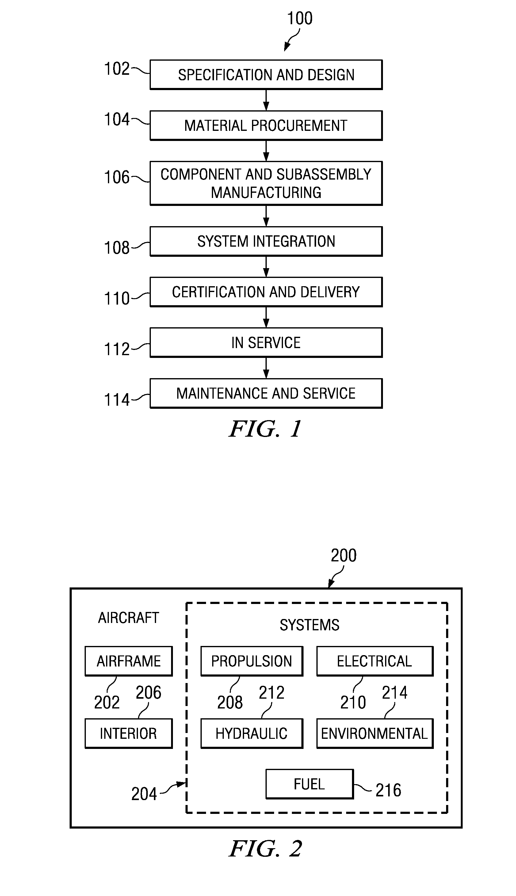
[0024]Referring more particularly to the drawings, embodiments of the disclosure may be described in the context of the aircraft manufacturing and service method 100 as shown in FIG. 1 and aircraft 200 as shown in FIG. 2. Turning first to FIG. 1, a diagram illustrating an aircraft manufacturing and service method is depicted in accordance with an advantageous embodiment. During pre-production, exemplary aircraft manufacturing and service method 100 may include specification and design 102 of aircraft 200 in FIG. 2 and material procurement 104. During production, component and subassembly manufacturing 106 and system integration 108 of aircraft 200 in FIG. 2 takes place. Thereafter, aircraft 200 in FIG. 2 may go through certification and delivery 110 in order to be placed in service 112. While in service by a customer, aircraft 200 in FIG. 2 is scheduled for routine maintenance and service 114, which may include modification, reconfiguration, refurbishment, and other maintenance or s...


PUM


Abstract

A method and apparatus for an optical fuel detection system. The optical fuel detection system comprises an outer tube, and inner tube, and a set of optical fibers. The outer tube has a reflective inner surface capable of reflecting light and is configured to allow a liquid fuel to enter an interior of the outer tube on which the reflective inner surface is located. The inner tube is located within the outer tube in which an area is present between the reflective inner surface. The set of optical fibers are mounted to an outer surface of the inner tube. Each optical fiber has a core that is exposed on each part of an optical fiber opposite to the reflective inner surface and the optical fiber has a refractive index that is lower that the liquid fuel but higher than a gaseous form of any gas that may enter the area.

Description

BACKGROUND INFORMATION[0001]1. Field[0002]The present disclosure relates generally to fiber optic devices and systems and in particular to a method and apparatus for detecting liquids. Still more particularly, the present disclosure relates to a method and apparatus for detecting fuel in a fuel tank.[0003]2. Background[0004]The amount of fuel present in an aircraft fuel tank is important for a pilot to know. The amount of fuel present can be used to verify fuel consumption of a flight. Measuring fuel levels in an aircraft fuel tank may be made using a fuel measurement system, such as a fuel gage. These systems include a sender unit and an indicator. The sending unit may be for example, a float connected to a variable resistor. The indicator may be an analog readout or a digital display of the amount of fuel present in the fuel tank.[0005]In an aircraft, a capacitive probe is as another example of a sender unit. Multiple probes may be mounted within the fuel tank in low voltage capac...

Claims


Application Information

Patent Timeline
Patent Type & Authority Applications(United States)
IPC IPC(8): G01F23/00
CPCG01F23/292Y02T50/672F02C7/22B64D37/005Y02T50/60
Inventor ANDERSON, STEVEN A.
Owner THE BOEING CO
Why Eureka
Try Eureka