
Pipeline Processing Method and Apparatus in a Multi-processor Environment

Inactive Publication Date: 2009-03-19
IBM CORP
View PDF3 Cites 32 Cited by
  • Summary
  • Abstract
  • Description
  • Claims
  • Application Information

AI Technical Summary

Benefits of technology

[0019]According to the above solutions of the present invention, dynamic-balancing of sub-tasks between multiple processors is achieved, thereby fully utilizing computation resources to achieve optimal gain of the multi-core processor.

Problems solved by technology

However, the traditional parallel programming model for data load-balancing cannot be adopted by DPI processing in certain cases.
An unfortunate fact is that, due to the existence of such things as VPN tunnels, network flow might be very “huge” in size or may even dominate the whole cable bandwidth.
The extreme case is that all packets are in a single tunnel flow and have to be processed in sequence, that is, cannot be well processed in parallel.
However, traditional pipeline programs suffer from very low adaptive ability so that the tasks have to be pre-partitioned and statically allocated to specific processors.
Note that the code path of each packet often differs from paths of the others, that is, a same DPI application may have differences for different packets, in particular sub-programs and computation resource requirements of each sub-program may be different, thus one can hardly expect that high resource utilization can be achieved by a static approach.
This is essential in the case of DPI, since even one percent loss in performance gain may lead to mismatch with performance.
Similarly, in the case of many applications other than DPI applications, there also exists a problem of how to make sub-tasks balance among multiple processors, regardless of the kind of task and the data to be processed.

Method used


Image

  • Pipeline Processing Method and Apparatus in a Multi-processor Environment
  • Pipeline Processing Method and Apparatus in a Multi-processor Environment
  • Pipeline Processing Method and Apparatus in a Multi-processor Environment

Examples


Embodiment Construction

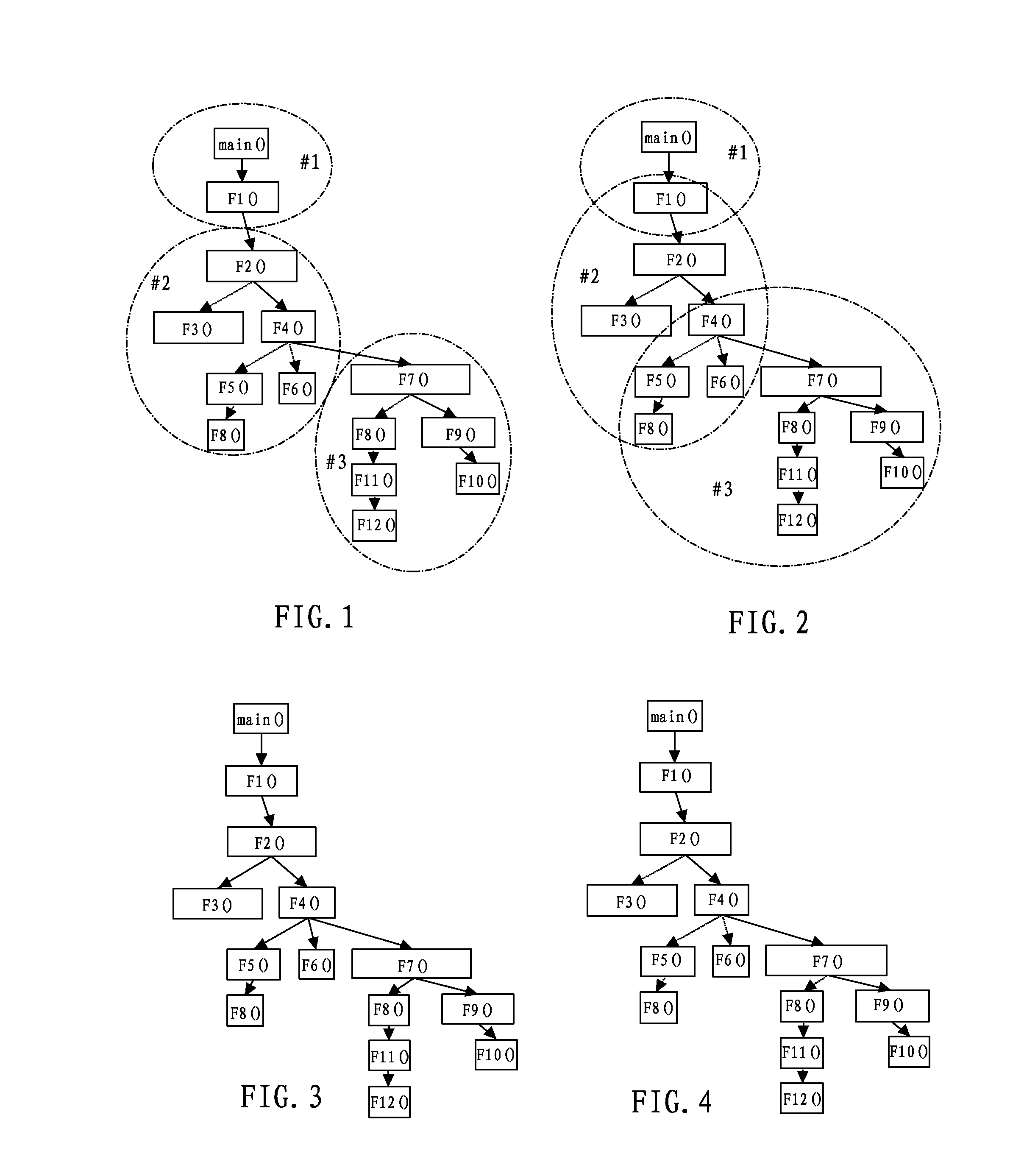
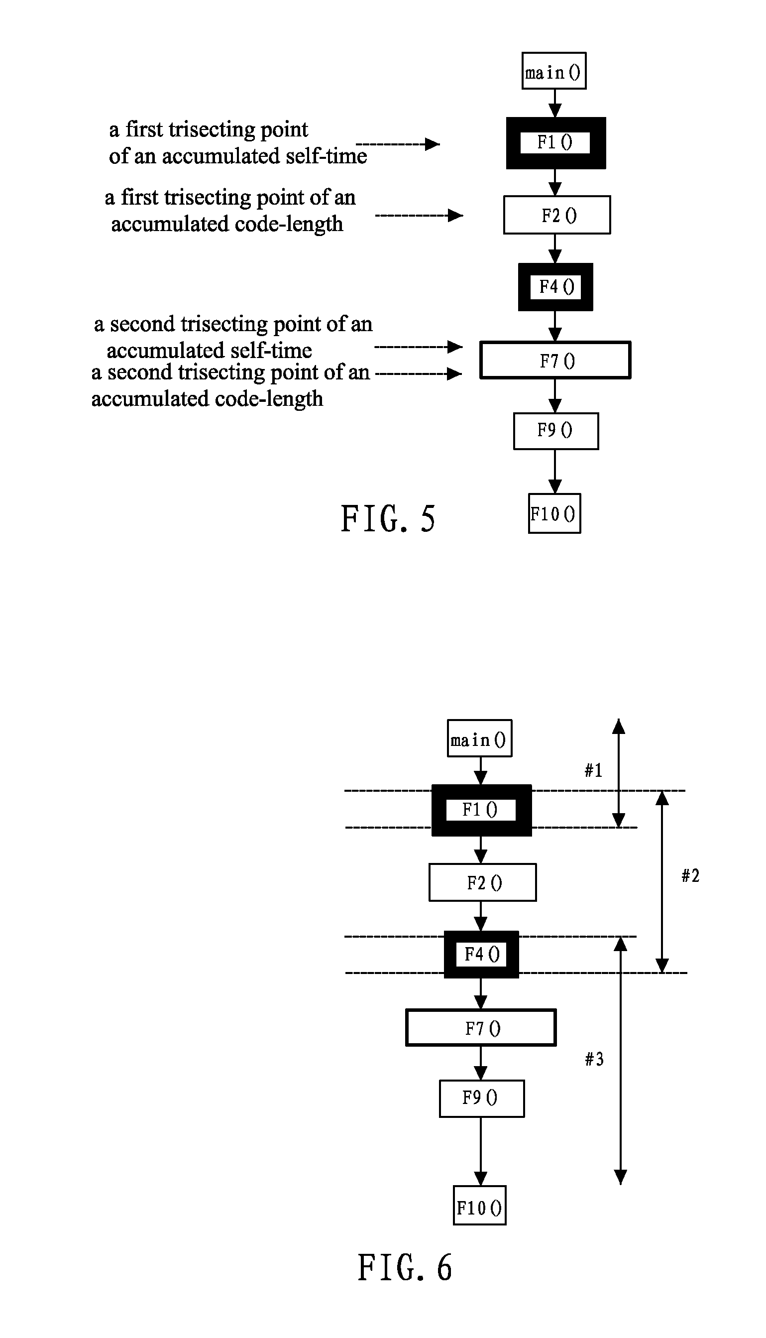
[0028]FIG. 1, as an example, is a call-graph of an application having eleven functions, routines main( ) and F1( ) to F10( ). A static partition is executed for the respective functions according to traditional pipeline processing techniques. For example, F1( ) is executed by processor #1, F2( ) to F6( ) and a further function call to F5( ) are executed by processor #2, F7( ) and function calls followed thereby are executed by processor #3. As recited in the background art, such static partitioning has a very low adaptive ability. Thus, in actual execution of an application, tasks of each of the processors may not be balanced as the processed data are different. For example, when F7( ) is not called by F4( ), processor #3 is idle for this application, while processor #2 needs to process more tasks than required when F7( ) is called by F4( ), that is, it needs to additionally process F5( ), F6( ), etc.

[0029]Therefore, regarding this problem, the present invention proposes a new pipel...


PUM


Abstract

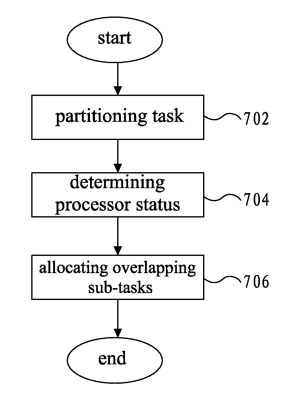
A pipelining processing method and apparatus in multi-processor environment partitions a task into overlapping sub-tasks that are to be allocated to multiple processors, overlapping portions among the respective sub-tasks being shared by the processors that process corresponding sub-tasks. A status of each of the processors is determined during a process where each of the processors executes sub-tasks and the overlapping portions among the respective sub-tasks to be executed by which processor among the processors is dynamically determined on the basis of the status of each of the processors.

Description

TECHNICAL FIELD[0001]The present invention relates to a pipelining technology, in particular, to a pipeline processing method and apparatus in a multi-processor environment.BACKGROUND ART[0002]DPI (Deep Packet Inspection), as a kind of emerging and popular-gaining network application, is performance sensitive. Its processing performance requirement proportionally relates to an interface wire-speed (since DPI deals with not only packet header but also packet payload).[0003]Multi-processor (multi-core or multi-chip, e.g. SMP, Symmetrical Multi-processor) is a promising approach to addressing the DPI performance issue for its turbo processing / computing power. However, the traditional parallel programming model for data load-balancing cannot be adopted by DPI processing in certain cases. The reason is that network communications are usually based on flow / session (the so-called “flow” means the packet stream between an arbitrary source-destination communication pair), and the respective ...

Claims


Application Information

Patent Timeline
IPC IPC(8): G06F9/50
CPCG06F9/5066
Inventor FENG, BOSHAO, LINGZHENG, KAI
Owner IBM CORP
Learn More