Residual torque analyzer

a technology of resistive torque and analyzer, which is applied in the direction of force/torque/work measurement apparatus, screws, instruments, etc., can solve the problems of under-torqued fasteners that can snap or strip their threads, shorten the extension of a tightening tool, and may vibrate or work loos

Active Publication Date: 2009-03-26
ASI DATAMYTE
View PDF25 Cites 33 Cited by
  • Summary
  • Abstract
  • Description
  • Claims
  • Application Information

AI Technical Summary

Benefits of technology

[0026]Further, the present invention is equally effective across all joint types, unlike known methods, including the capture angle method, and does not require estima

Problems solved by technology

For example, an under-torqued fastener may vibrate or work loose.
Conversely, if tension is too high, the fastener can snap or strip its threads.
First, there are dozens of sources of error that could cause an instrumented tool, one that initially indicated correct installation torque, to subsequently apply low actual joint torque.
In another example, a longer-than-normal extension used with a tightening tool may introduce error.
The longer extension absorbs more rotational energy intended for the joint as compared to a shorter extension, thus lowering actual applied torque.
As the gears in the right-angle drive of a power wrench collect dirt and wear, increasing friction absorbs torque and the sensor in the tool picks up less than accurate readings.
A second reason to precisely measure residual torque is the high cost of failure for many joints.
Improper torque in safety-critical applications, such as steering gears or braking assemblies, can result in significant equipment damage, human injury, or even death.
In order for these devices to effectively and accurately measure residual torque, though, a significant amount of operator training and practice is required.
The tendency to overshoot is central to many of the problems associated with using a simple peak-reading device, such as the one disclosed in Becker et al., to measure residual torque.
Slower reaction time results in greater overshoot.
In addition, since torque auditors typically take several hundred measurements in a shift, inconsistencies may creep into the process.
Fatigue may cause a weaker pull on the wrench, or pressure to meet a schedule may lead to a quicker pull and greater overshoot.
Whil

Method used


Image

  • Residual torque analyzer
  • Residual torque analyzer
  • Residual torque analyzer

Examples


Embodiment Construction

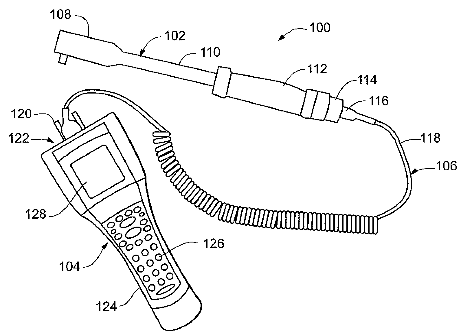
[0050]Referring to FIG. 6, in one embodiment, the present invention is a torque analyzer 100 that includes torque-angle wrench 102, data collector-analyzer (DCA) 104, and communication cable 106. Although depicted as separate components, it will be appreciated that in some embodiments, torque-angle wrench 102 and DCA 104 may be integrated to form torque analyzer 100, thereby eliminating the need for communication cable 106.

[0051]Referring to FIGS. 6-8, torque-angle wrench 102 includes head assembly 108, shaft 110, handle 112, and connector 114. In one embodiment, head assembly 108 includes circuit board assembly 132, cover plate 140, screws 142, torque transducer 134, and socket retainer 146. Head assembly 108 defines an electronics cavity 130 that houses circuit board assembly 132. As will be discussed in further detail below, circuit board assembly 132 includes gyroscope 136 and indicating LED 138. Cover plate 140 covers an opening of cavity 130 to enclose circuit board assembly 1...


PUM


Abstract

A system for detecting fastener movement and measuring a residual torque in a fastener joint, including a device for applying torque to a stationary fastener in a tightened state and measuring torque and angle of rotation. The device includes a sensing system that has a gyroscope that provides a signal corresponding to the angle of rotation of the device as it applies torque to the fastener, and a torque transducer that provides a signal corresponding to the torque applied to the fastener by the device. The device also includes a computing unit in communication with the sensing system and adapted to receive the signal corresponding to an angle of rotation of the device and the signal corresponding to the torque applied to the fastener, and determine a torque at a moment of initial movement of the fastener.

Description

RELATED APPLICATION[0001]This application claims the benefit of: U.S. Provisional Application No. 60 / 994,624, entitled IMPROVED RESIDUAL TORQUE MEASUREMENT, filed Sep. 20, 2007; U.S. Provisional Application No. 60 / 994,837, entitled TORQUE WRENCH WITH ANALOG OR DIGITAL OUTPUT CAPABILITY, filed Sep. 21, 2007; and U.S. Provisional Application No. 60 / 995,021, entitled TORQUE ANALYZER SYSTEM, filed Sep. 24, 2007, all of which are incorporated herein in their entirety by reference.FIELD OF INVENTION[0002]The invention relates generally to residual torque detection and analysis. More specifically, the invention relates to devices, systems and methods relating to measuring residual torque in a previously-tightened fastener by detecting fastener motion.BACKGROUND OF THE INVENTION[0003]Residual torque may be defined as the torque that remains on a threaded fastener after it has been tightened, and is typically measured by applying torque to the previously-tightened fastener and observing the ...

Claims


Application Information

Patent Timeline
IPC IPC(8): G01L5/24
CPCB25B23/1425B25B23/14
Inventor SCHULTZ, JIM P.SKOG, FRANK I.TAIT, DAVID A.ERICKSON, STEVEN D.NELSON, CECIL H.
Owner ASI DATAMYTE
Why Eureka
Try Eureka