Hummingbird feeder with flying insect control

Inactive Publication Date: 2009-03-26
CHARLTON THOMAS
View PDF5 Cites 44 Cited by
  • Summary
  • Abstract
  • Description
  • Claims
  • Application Information

AI Technical Summary

Benefits of technology

[0005]Since the nectar level in the base is determined by the mating of the bottom of the upper reservoir container with the lower reservoir nectar

Problems solved by technology

Another problem is the presence of people sometimes irritates the insects resulting in painful stings.
I had considered poisons and

Method used


Image

  • Hummingbird feeder with flying insect control
  • Hummingbird feeder with flying insect control
  • Hummingbird feeder with flying insect control

Examples


Embodiment Construction

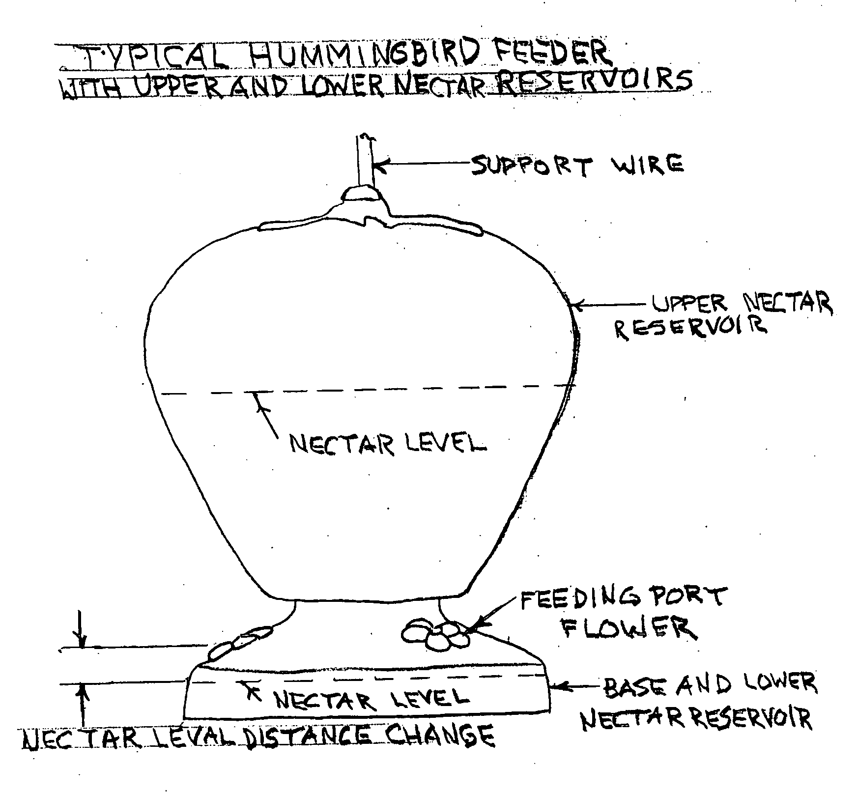
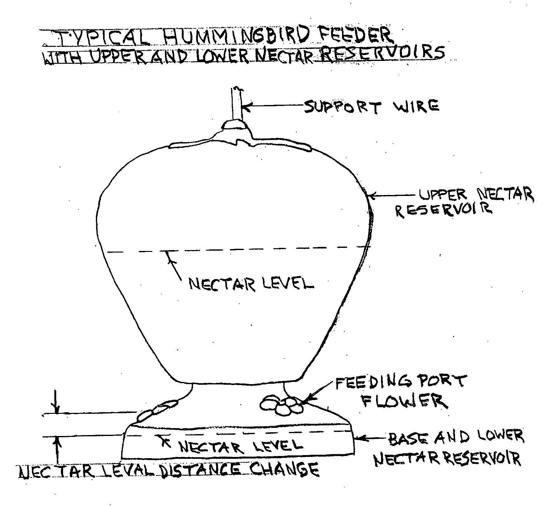
[0008]The purpose of this invention is to eliminate the presence of flying insects at hummingbird feeders. This causes a nuisance to people resulting in painful stings and excessive consumption of nectar by these insects, resulting in additional nectar expense. Swarms of flying insects prevent the hummingbirds from normal feeding.

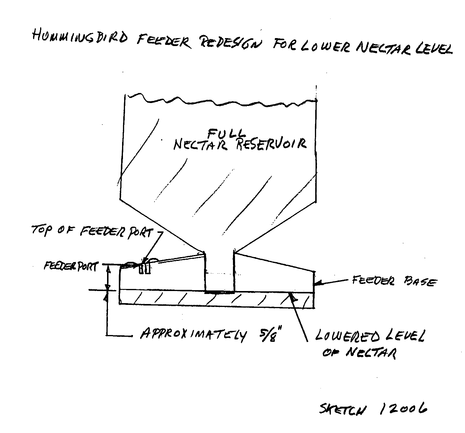
[0009]These objectives are accomplished by reducing the nectar level in the feeder base to an extent that the flying insects' proboscis cannot reach the nectar. This is accomplished by lowering the position of the upper nectar reservoir relative to the base by approximately one fourth inch (¼″) which increases the distance from the feeding port flower to the nectar level to approximately five eights inch (⅝″), which is out of the reach of the flying insects' proboscis. When the flying insects can no longer feed on the nectar, they quit visiting the feeder. This modification is accomplished by changing the base plastic mold to reduce the nectar level.

[0010]T...


PUM


Abstract

This invention entails the re-design of existing hummingbird feeders that have an upper nectar reservoir with mating base holding the lower nectar reservoir. Please refer to Drawing SKETCH 12006 This is a re-designed hummingbird feeder that lowers the base nectar level approximately one fourth inch (¼″) and out of reach of flying insects, thus eliminating their presence and removing the nuisance and the possibility of painful stings to people. This is a re-designed hummingbird feeder that eliminates the presence of flying insects and their robbing of nectar, thus reducing the expense of nectar.

Description

SPECIFICATION / DESCRIPTION[0001]The re-designed hummingbird feeder is a design that has a reservoir for nectar mounted above the base that contains the lower nectar reservoir. The nectar level in the base is fixed by the base design. The top reservoir is an inverted container similar to a bottle that when the top reservoir is filled, and the bottom is empty, the level in the lower reservoir fills until the level reaches the level of the bottom of the upper reservoir. The level stays there because of atmospheric pressure. When nectar is removed the nectar is replaced by the upper reservoir until the previous fixed level is reached and atmospheric pressure stops the process. The re-design can only be used on this type hummingbird feeder. Please refer to included drawing EDSK 200718.CROSS-REFERENCE TO RELATED APPLICATIONSNot ApplicableSTATEMENT REGARDING FEDERALLY SPONSORED RES. & DEV.Not ApplicableREFERENCE TO SEQUENCE LISTING, A TABLE, OR A COMPUTER CDNot ApplicableBACKGROUND OF THE I...

Claims


Application Information

Patent Timeline
IPC IPC(8): A01K39/026
CPCA01K39/0113A01K39/026A01K39/0206A01K39/02
Inventor CHARLTON, THOMAS
Owner CHARLTON THOMAS
Why Eureka
Try Eureka