Conveying device
- Summary
- Abstract
- Description
- Claims
- Application Information
AI Technical Summary
Benefits of technology
Problems solved by technology
Method used
Image
Examples
Embodiment Construction
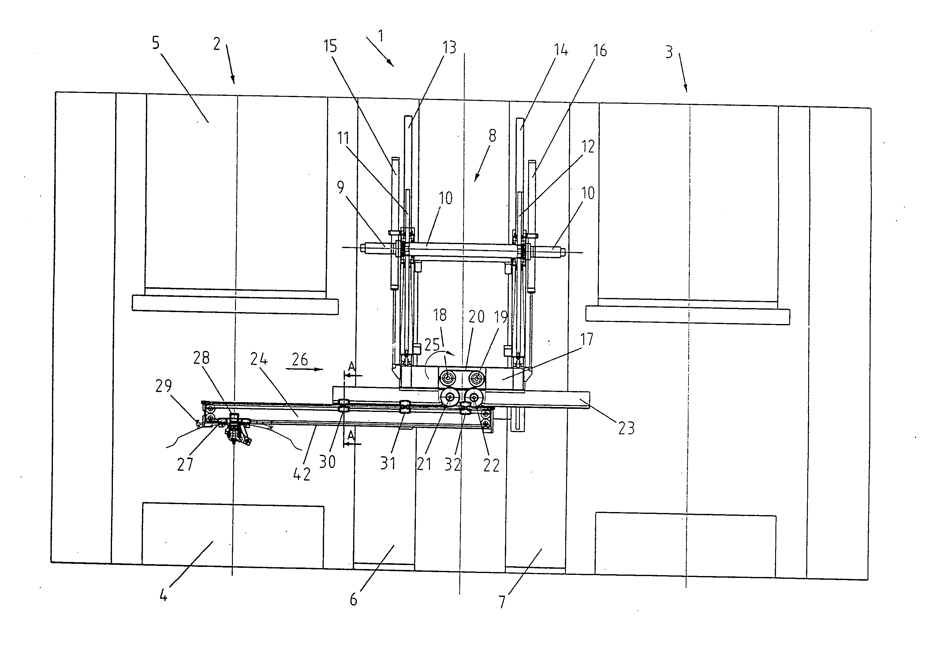
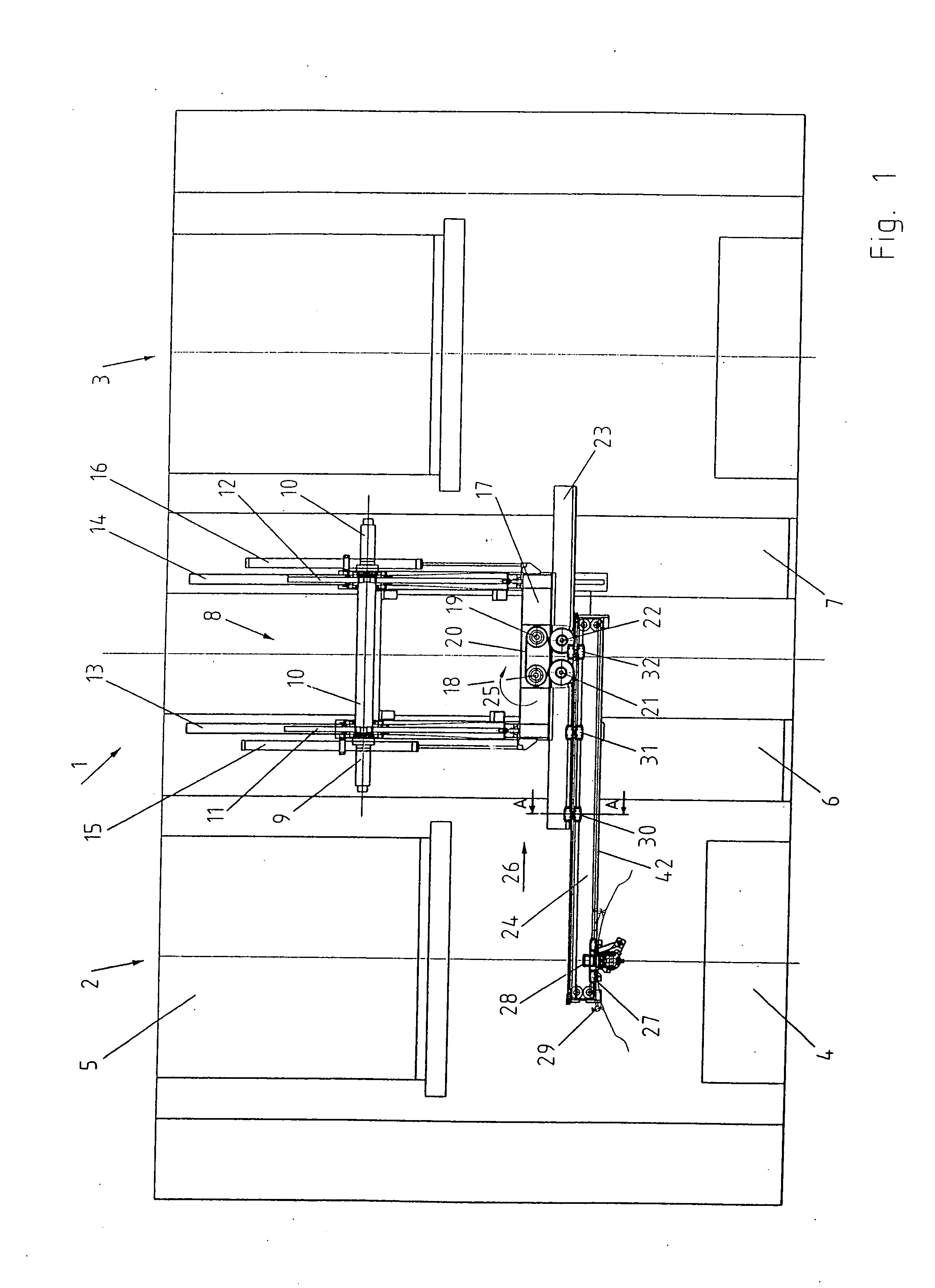
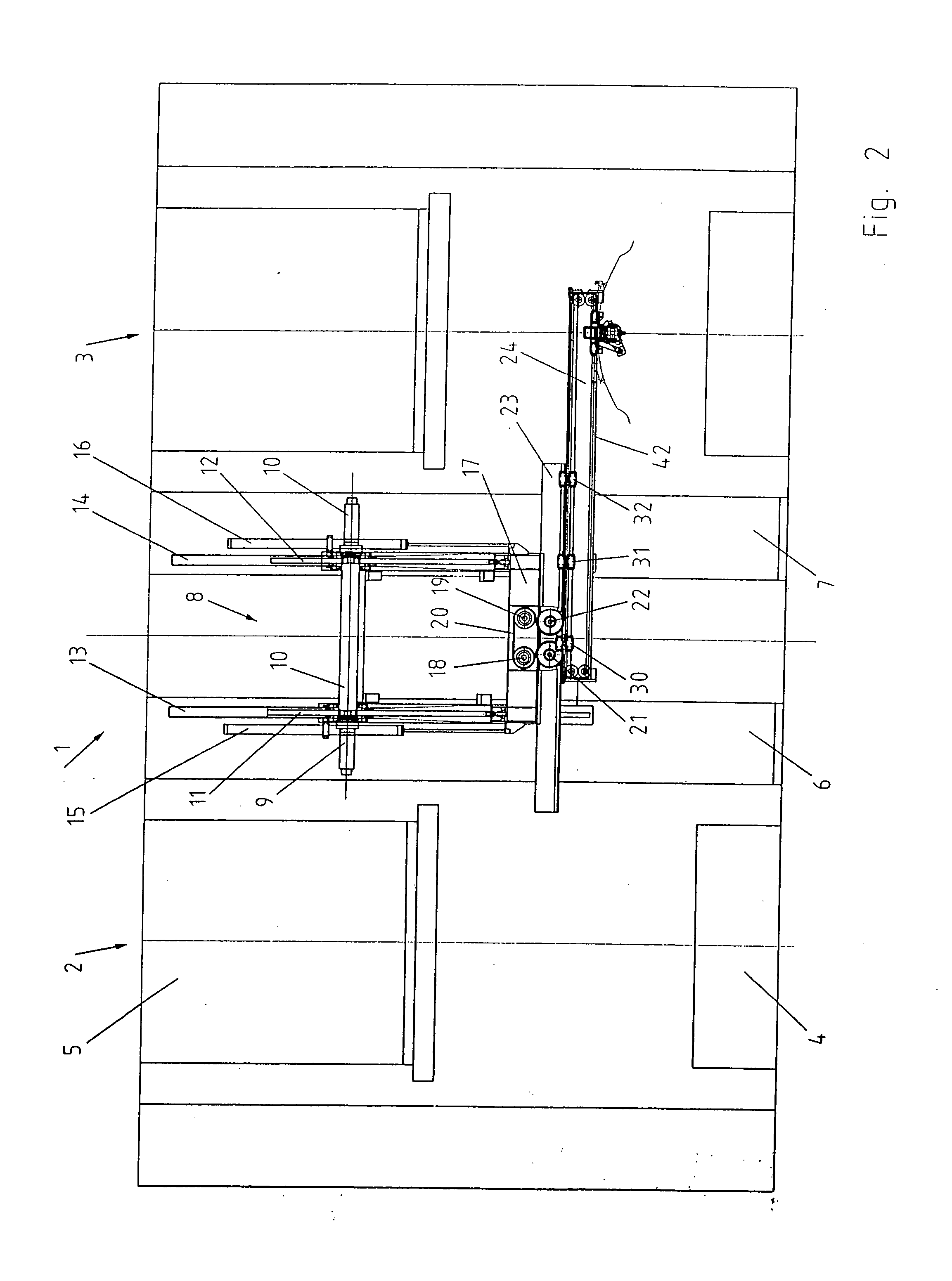
[0020]FIG. 1 depicts partial views of the shaping areas of the presses 2 and 3 in a simplified depiction of a press line 1. The sliding table 4 and the ram 5 can be seen. The punch and die are not shown in greater detail. The telescoping feeder 8 is attached to the press uprights 6, 7. Fixed, controllable motors 9, 10 effect the drive for the vertical movement and act via pinion gears on racks 11, 12. Linear guides 13, 14 assure certain vertical guidance. Forced synchronization of the lift movement is attained using the connecting shaft 41. For unloading the drives 9, 10, the masses to be moved can be compensated by cylinders 15, 16.
[0021]The racks 11, 12 are joined to the transverse crossmember 17 on which are arranged the motors 18, 19 that drive a toothed belt 20. For reasons of functional security, two motors are suggested 18, 19 so that if one of the motors fails the telescoping feeder can be moved out of a potential collision area using the second motor.
[0022]The toothed belt ...
PUM
 Abstract
Description
Claims
Application Information
 - R&D
- Intellectual Property
- Life Sciences
- Materials
- Tech Scout
- Unparalleled Data Quality
- Higher Quality Content
- 60% Fewer Hallucinations
Browse by: Latest US Patents, China's latest patents, Technical Efficacy Thesaurus, Application Domain, Technology Topic, Popular Technical Reports.
© 2025 PatSnap. All rights reserved.Legal|Privacy policy|Modern Slavery Act Transparency Statement|Sitemap|About US| Contact US: help@patsnap.com


