Electro-optical imaging reader having plural solid-state imagers with shutters to prevent concurrent exposure

a technology of optical imaging and shutters, applied in hybrid readers, visual presentation, instruments, etc., can solve the problems of slowing down transaction processing and reducing productivity, affecting the ability of illuminators to read indicia, and reducing the ability of illuminators to interfere or crosstalk, etc., to achieve enhanced reading capability, high density, and increased resolution

Active Publication Date: 2009-03-26
SYMBOL TECH LLC
View PDF23 Cites 59 Cited by
  • Summary
  • Abstract
  • Description
  • Claims
  • Application Information

AI Technical Summary

Benefits of technology

[0017]One feature of this invention relates, briefly stated, to a reader for, and a method of, electro-optically reading indicia, comprising a plurality of controllable image capture modules at a housing and operative for capturing images of the indicia along different fields of view. Each module includes an illuminator for illuminating the indicia with illumination light. Each module further includes a solid-state imager with a rolling shutter for sequentially capturing return illumination light from the indicia. Preferably, the imager is a two-dimensional array of megapixel size for increased resolution and enhanced capability for reading indicia, such as symbols of high density. Each module still further includes a shutter element for passing the return illumination light from its illuminator to its imager in an open state, and for blocking the return illumination light from other illuminators of other modules from reaching its imager in a closed state. Preferably, each shutter element is a physical device movable between the open and the closed states. Advantageously, the physical device is a hinged gate mounted on each module for pivoting movement between the open and the closed states.

Problems solved by technology

In typical “blind-aiming” usage, it is not uncommon for the operator to repeatedly swipe or present a single symbol several times before the symbol is successfully read, thereby slowing down transaction processing and reducing productivity.
The blind-aiming of the symbol is made more difficult because the position and orientation of the symbol are variable.
If the exposure time periods from any two imagers are concurrent, then interference or crosstalk among the illuminators can be caused by multiple internal reflections from the field mirrors within the reader.
The illuminated image being captured by any one imager may be corrupted by light associated with another imager.
Also, the possibility of uneven illumination could occur if more than one set of illumination LEDs is energized at the same time.
In addition, the peak current consumption of the entire reader may be too high if more than one set of illumination LEDs are energized at the same time.
MP imagers with global shutters are available, but at a prohibitively high cost, especially when multiple imagers are required in the reader.
This rolling action, however, can cause undesirable exposure at each imager to illumination from other illumination light sources from the other imagers, thereby degrading the captured image by such crosstalk.

Method used


Image

  • Electro-optical imaging reader having plural solid-state imagers with shutters to prevent concurrent exposure
  • Electro-optical imaging reader having plural solid-state imagers with shutters to prevent concurrent exposure
  • Electro-optical imaging reader having plural solid-state imagers with shutters to prevent concurrent exposure

Examples


Embodiment Construction

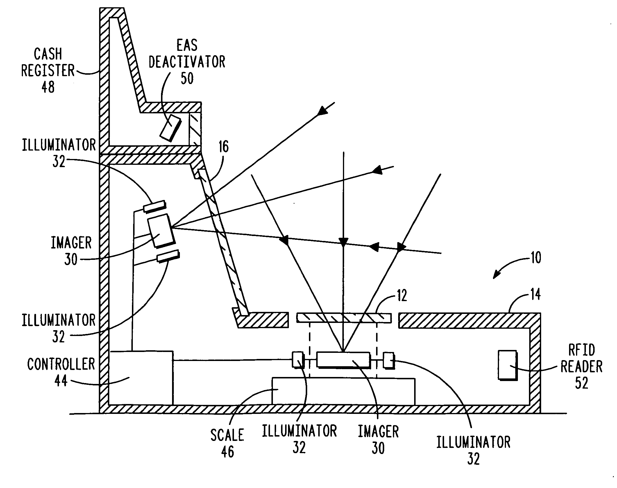
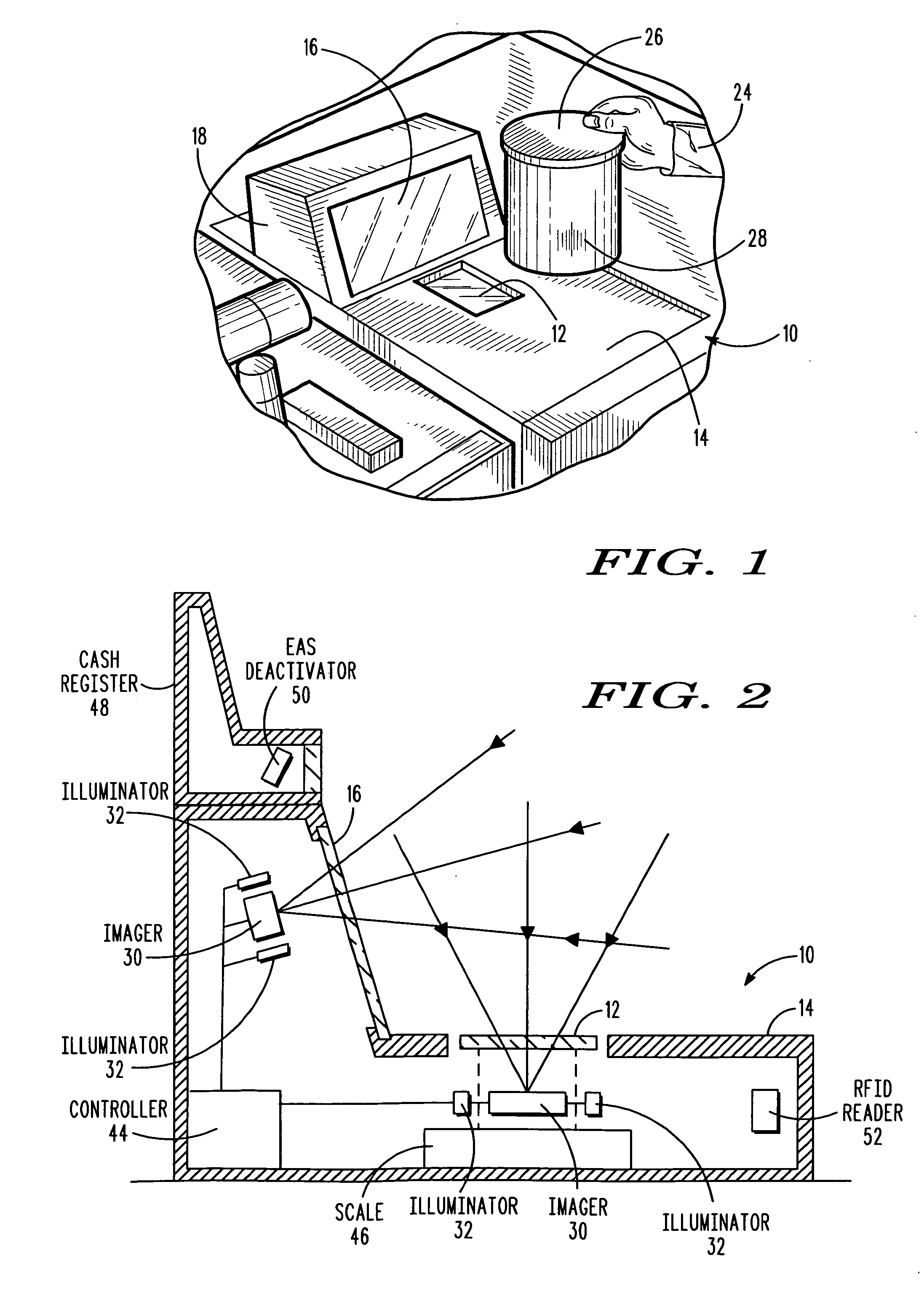
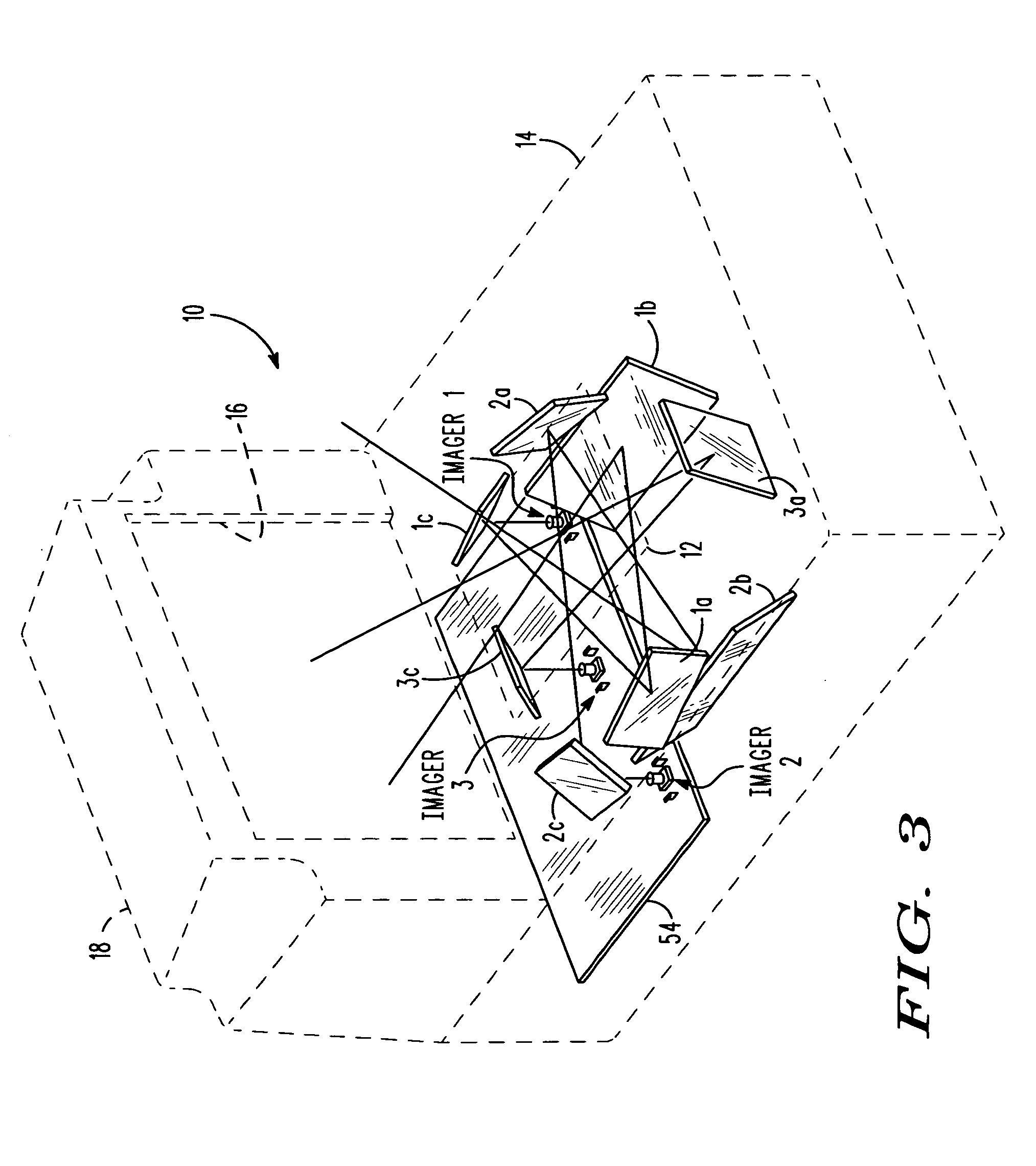
[0033]FIG. 1 depicts a dual window, bioptical, point-of-transaction workstation 10 used by retailers to process transactions involving the purchase of products bearing an identifying target, such as the UPC symbol described above. Workstation 10 has a generally horizontal window 12 set flush with, or recessed into, a countertop 14, and a vertical or generally vertical (referred to as “vertical” or “upright” hereinafter) window 16 set flush with, or recessed into, a raised housing portion 18 above the countertop.

[0034]As schematically shown in FIG. 2, a plurality of imaging modules, each including a solid-state sensor or imager 30 and an illuminator 32, is mounted at the workstation, for capturing return light passing through either or both windows from a target or indicia, which can be a one- or two-dimensional symbol, such as a two-dimensional symbol on a driver's license, or any non-symbol target, as described below. Each imager 30 is a solid-state array, preferably a charge coupl...


PUM


Abstract

A bioptical workstation includes plural image capture modules for capturing images of indicia along different fields of view. Each module includes an illuminator for illuminating the indicia with illumination light, a megapixel imager with a rolling shutter for sequentially capturing the return light, and a shutter element for passing the return light to its imager in an open state, and for blocking the return light from other modules from reaching its imager in an closed state. A controller prevents interference among the modules by controlling the shutter element to assume the open state only during a respective exposure time period during which its imager produces an electrical signal indicative of the indicia, and by controlling the shutter element to assume the closed state at all times other than the respective exposure time period to prevent capture of the return light from the other modules.

Description

CROSS REFERENCE TO RELATED APPLICATION[0001]This application is a continuation-in-part of U.S. patent application Ser. No. 11 / 823,818, filed Jun. 28, 2007, now pending.BACKGROUND OF THE INVENTION[0002]Flat bed laser readers, also known as horizontal slot scanners, have been used to electro-optically read one-dimensional bar code symbols, particularly of the Universal Product Code (UPC) type, at a point-of-transaction workstation in supermarkets, warehouse clubs, department stores, and other kinds of retailers for many years. As exemplified by U.S. Pat. No. 5,059,779; U.S. Pat. No. 5,124,539 and U.S. Pat. No. 5,200,599, a single, horizontal window is set flush with, and built into, a horizontal countertop of the workstation. Products to be purchased bear an identifying symbol and are typically slid across the horizontal window through which a multitude of scan lines is projected in a generally upwards direction. When at least one of the scan lines sweeps over a symbol associated with...

Claims


Application Information

Patent Timeline
Patent Type & Authority Applications(United States)
IPC IPC(8): G06K7/10
CPCG06K7/0004G06K7/10762G06K7/10732G06K7/10722
Inventor GIEBEL, JAMESBARKAN, EDWARDBROCK, CHRISTOPHER WARRENDRZYMALA, MARKVINOGRADOV, IGOR
Owner SYMBOL TECH LLC
Why Eureka
Try Eureka